LED Cube/Assembly and Testing
| LED Cube Series | |
|---|---|
|
| |
|
Chapter 1: Build Section 0: Preparation and Requirements Section 1: PCB Soldering Manual Section 2: Cube Soldering Manual Section 3: Assembly and Testing | |
|
Chapter 2: Play | |
|
Chapter 3: Learn |

This page helps you to assemble cube structure and PCB to the fully functional LED Cube.
Connecting the Cube to Your PCB[Bearbeiten]
You should have already prepared the LED Cube PCB prior to the cube structure. If not, you probably want to do this now: LED Cube/PCB Soldering Manual.
Now: It may be a good idea to take the orientation of this cube into consideration. One of the horizontal wires of the planes is most outside. You can tell this from this picture:

In this case, it is the side pointing away from you. Try to get this side on the same side as the USB connector on the PCB. It will then look like this:


Now, you already made your choice if you wanted to use connectors for the cube or not. If you are not using connectors, simply solder your cube to the PCB. If you are using connectors you may plug your cube in now or read what we have to say about this:
Connecting the cube to the pcb may be quite tedious, depending on the accuracy of your cube structure. We suggest you follow this procedure:
-
Plug the three legs on one side of the cube into their connectors. Make sure they are really plugged in. Maybe you have to use some pliers or extremely carefully apply pressure to the bottom LED. You can do this by lifting up your construction at the cube: If it is already able to lift up the PCB, everything is okay.
-
-
Now carefully lift up the legs in the adjacent row and put them into their connectors - but don't plug them in completely as you did with the previous row. This should leave the last row floating above their connectors.
-
-
Now carefully insert the legs of the center row completely, one by one. While doing this, make sure that the connectors of the last row are sliding into their connectors, too. They will however, as already mentioned above, not completely enter the connectors. After you inserted all connectors of the center row, completely plug in the connectors of the last row. The cube should then be plugged into all connectors:
-


Adding the Plane Connectors[Bearbeiten]
Now we know how the cube is positioned on the PCB. The final soldering step is to add the connectors for the planes. If you remember - the wires that are currently holding the planes together are not yet connected to the PCB. To fix this, get some (silver enameled copper) wire. Turn the LED cube, so you look directly onto the USB connector. Then cut one so it is at least long enough to reach from the PCB to the top plane.


Plug this piece of wire into the rightmost free connector of CONN10, if you are using connectors, or solder it into the PCB at the same place, if not. Bend the wire so that it touches the top plane and solder them together:

Repeat this step for the center pin of the connector and the plane in the middle and the leftmost pin of the connector and the bottom plane:

Inserting the Microcontroller[Bearbeiten]
Get the microcontroller and make sure the leads are bent like the ones of the transistor array. Put it into the socket, taking care that the two notches align.
-
the microcontroller
-
correctly bent legs
-
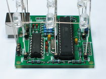
microcontroller inserted into the socket


Optical Inspection[Bearbeiten]
It is now time to inspect your cube for any shorts. Depending on your testing equipment, you should do this more or less thoroughly, but it is always a good idea. Get a magnifier if your eyes are too bad for it.
Programming the Bootloader[Bearbeiten]
|
If you are taking part in a cccgoe workshop or bought a kit with a pre-flashed microcontroller, skip this step! |
If you do not have a pre-flashed microcontroller, you should now either
- add the ISP header to the PCB and we will flash the bootloader later or
- flash the microcontroller outside of the PCB.
Do whatever you like.
Test Setup[Bearbeiten]
|
If you are at a cccgoe workshop, you can (or should) replace this section by going to one of the tutors. He will do the testing with you and (if he is in a good mood) explain to you what exactly he is doing. |
Now comes the exciting part. We will test if you did everything wrong. This section is divided into several sections. Please pick the one you can perform. The tests are ordered in the following way: Try to do the one on the top. If you do not have the equipment for this, skip to the next test below that and so on. If you have completed one test, you may skip all tests below that one.
Before starting any test, make sure the bootloader jumper is in the following position:

|
Please Note: The device you created is your own. We can not accept responsibility for any defects this causes to your USB Host, Hub or any other Device on the same bus. If you are unsure whether to take any risks, do not take them! |
Test 1: Laboratory Power Supply and USB Isolator[Bearbeiten]
This is the safest test described here. It is also the test that will be performed at cccgoe workshops. You need
- A USB Isolator capable of USB 1.1,
- a Laboratory Power Supply and
- a way to connect the power supply to your isolator.
Now connect your assembled LED Cube to the A port of your isolator. Set the isolator to low speed mode (if necessary). Connect the computer you want to test the device with to the B port of your isolator.
Turn on the laboratory power supply, make sure the outputs are turned off. Tet the current limit to about 40 mA. Set the voltage limit to 5 V. Connect the power supply output to the isolator.
The test starts once you enable the power supply. You should skip to #Test Evaluation before you start it.
Test 2: Laboratory Power Supply and USB Hub[Bearbeiten]
If you only have a laboratory power supply, you have to take a USB cable, you have to find a way to inject this as the power supply voltage. To do so, get a USB cable and carefully cut away the outer plastic isolation layer for a length of about 2 cm near the B connector. Fiddle away the shield, but do not cut it completely. Get the black and the red wire, cut them near the host side of your opening in the cable. You can now connect your power supply to these cables.
Set up the power supply as in Test 1. The test starts once you enable the output, but first go to #Test Evaluation to read about how to evaluate the results.
Test 3: A POWERED USB Hub[Bearbeiten]
This is probably the easiest test, but it may cost you a USB hub or a USB hub power supply. This severely lowers the risk of damaging your computer in contrast to connecting it directly. Simply connect a hub to your computer and supply power to your hub using a separate mains adapter. The test begins once you connect the your LED Cube to your USB hub. However, first go to #Test Evaluation and learn how you can evaluate the results.
Test 4: On an Old Computer, If Nobody Will Care If It Breaks[Bearbeiten]
You can also us an old computer, if it does not matter if it breaks. The test starts once you connect the LED Cube to the computer. However, first read #Test Evaluation to understand how to interpret the results.
Test 5: On a New Computer[Bearbeiten]
Don't. Get at least a USB Hub. Really. This is no joke. However, in general it should be possible. But you know how unforgiving USB hardware is and though it should not damage your computer, it probably will.
Test Evaluation[Bearbeiten]
If the current consumption stays within the 40 mA, the computer didn't turn off and none of the mains adapters blew, nothing catastrophic happened - probably.
|
If you do not have a pre-flashed microcontroller: Now is the time to connect your In-System Programmer and flash the bootloader onto the microcontroller. You will find how to build the bootloader in LED Cube/Building From Source. |
You should now be able to see a line in your kernel log that looks like this:
[158825.185016] generic-usb 0003:16C0:05DF.000E: hiddev0,hidraw0: USB HID v1.01 Device [obdev.at HIDBoot] on usb-0000:00:1d.0-1.1.4.3/input0
The windows users amongst you should get a notification about a new USB device, but not be asked to install drivers.
|
If you did not have a pre-flashed microcontroller: You have to use bootloadHID to add a firmware to your cube to fully test it. |
Those of you who have a laboratory power supply with current limiting, should now increase their current limit to 200 mA.
Now remove the bootloader jumper. The default firmware for all microcontrollers is a firmware that turns on every single LED. You can have a look at the reference cube performing this animation here: (youtube).
|
Well, you've finished building your cube. Now it's time to play with it. However, you should continue reading the usage manual first. |