LED Cube/Cube Soldering Manual: Unterschied zwischen den Versionen
Marvin (Diskussion | Beiträge) |
Sdx23 (Diskussion | Beiträge) KKeine Bearbeitungszusammenfassung |
||
| (8 dazwischenliegende Versionen von einem anderen Benutzer werden nicht angezeigt) | |||
| Zeile 1: | Zeile 1: | ||
{{ | {{LED Cube Series/en}} | ||
This page of the [[LED Cube]] Series will guide you through the process of building the Cube structure of the LED Cube. Building this structure is not really hard, but it may be a bit frustrating if the wires do not want like you. This is normal and your first cube will most probably not look perfect. However, this is a beginner workshop, so there will be much to learn. | This page of the [[LED Cube]] Series will guide you through the process of building the Cube structure of the LED Cube. Building this structure is not really hard, but it may be a bit frustrating if the wires do not want like you. This is normal and your first cube will most probably not look perfect. However, this is a beginner workshop, so there will be much to learn. | ||
| Zeile 21: | Zeile 21: | ||
</gallery> | </gallery> | ||
==LED Bending== | ==LED Bending== | ||
In the second step we have to bend the legs of the LEDs so you can assemble them without much mechanical stress on the wires. Be careful with the next steps - they are deciding | In the second step we have to bend the legs of the LEDs so you can assemble them | ||
without much mechanical stress on the wires. Be careful with the next steps - | |||
they are deciding what your cube looks like. Also, try to bend the wires | |||
correctly the first time and do not wiggle much on them, they tend to break off if you overdo it. | |||
===Short Leg=== | ===Short Leg=== | ||
First, take one LED: | First, take one LED: | ||
| Zeile 143: | Zeile 146: | ||
</gallery> | </gallery> | ||
That's nearly it! At least the hardest part is done. | That's nearly it! At least the hardest part is done. | ||
Now | {{Continue|Now that you've soldered the cube structure, you should continue with [[LED Cube/Assembly and Testing|Section 3: Assembly and Testing]].}} | ||
Aktuelle Version vom 4. Mai 2012, 15:44 Uhr
| LED Cube Series | |
|---|---|
|
Chapter 1: Build Section 0: Preparation and Requirements Section 1: PCB Soldering Manual Section 2: Cube Soldering Manual Section 3: Assembly and Testing | |
|
Chapter 2: Play | |
|
Chapter 3: Learn |
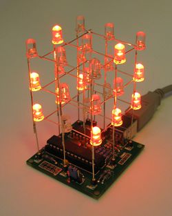
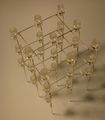
This page of the LED Cube Series will guide you through the process of building the Cube structure of the LED Cube. Building this structure is not really hard, but it may be a bit frustrating if the wires do not want like you. This is normal and your first cube will most probably not look perfect. However, this is a beginner workshop, so there will be much to learn.
LED Preparation[Bearbeiten]
How this first step will look somewhat depends on your LEDs. For now we will only clear LED bodies with one color:
Thus, if you have matt LEDs, you do not have to care about this step.
The clear see-through LEDs have a big advantage over the matt ones: You can see through them and thus the illusion of free hanging lights is much better. However, they also have a notable disadvantage: They have a very small cone of light coming out at the top. This makes it nearly impossible to look into them from above, they nearly don't shine from the side and LEDs from below will also illuminate LEDs above them. A very good workaround at this point is to grab a sheet of fine sand paper and to sand the top surface of the LED. Here you can see the difference:
Repeat this step with all LEDs, if you want. Try not to bend the legs to much, as this will on one hand stress them and on the other hand make your cube look less regular. (Of course, you may want such a cube - that is your decision. ;) .)
LED Bending[Bearbeiten]
In the second step we have to bend the legs of the LEDs so you can assemble them without much mechanical stress on the wires. Be careful with the next steps - they are deciding what your cube looks like. Also, try to bend the wires correctly the first time and do not wiggle much on them, they tend to break off if you overdo it.
Short Leg[Bearbeiten]
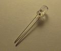
First, take one LED:
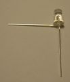
Hold it upside down and make sure that the longer of the two legs is the left one, the shorter the right one. Then bend the shorter 90 degrees towards you. The result should look like this:
Repeat this step for all LEDs check twice that you bent the correct leg. If you are using the wrong ones, the LED will not work.
Long Leg[Bearbeiten]
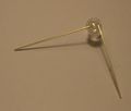
Again for all LEDs repeat the following steps: Take one LED and hold it like you did last time. This time, of course, the short leg is already bent to you. The long leg on the left side now is to be bent 90 degres to the left. The result will look like this:
Now take a pair of (flat nose) pliers and grab the same leg directly where the LED body ends:
And bend it back up. The long leg is now going into the same direction as prior to this step, but shifted away from the LED:
Don't forget to repeat this step for every LED:
Assembling the Planes[Bearbeiten]
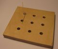
We have nearly finished preparing the LEDs. It is now time to assemble the planes. To get to the plane, we will first assemble a single row. A very handy tool for this is a plate with holes drilled into it where the LEDs belong.
Just insert the first LED into the top left corner of the plate, with the legs oriented like this:
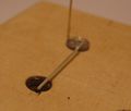
Now cut the horizontal leg at the point where it has completely passed the adjacent hole:
Into the hole that is passed by the leg from the first LED, insert the next LED like this:
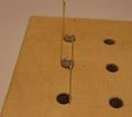
Again, cut the leg just after it passed the next hole:
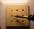
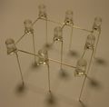
Add the third LED like this and solder the legs together at the second and third LED:
The end result will look like this:
Now cut the leg of the lowest LED directly after the solder joint:
Repeat these steps to create the next two rows:
Take two pieces of (preferably silver-enameled copper) wire that are long enough to fit across the cube:
Solder all three joints of the three wires with the horizontal wires. Make sure these wires do not touch the vertical wires.
Cut away the any excess wire:
After you removed the construction from the plate you have the first plane ready. Carefully wiggle a bit on the long legs to check if all the solder joints are holding. If they don't, redo them.
Repeat this step for the next two planes so you have three planes before you continue.
Assembling the Cube[Bearbeiten]
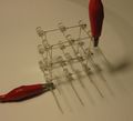
Now you should three have at least somewhat identical planes. The next step is obviously to join them to a cube. It is a good idea to fixiate two planes together, before trying to solder. We do this with alligator clips:
Make sure the planes are oriented the same way, if not, the LEDs will be shifted. Now just solder all nine joints. You may have to bend some wires a bit until they match:
Make sure you soldered all nine joints, especially the middle one. To fix this may be difficult, depending on your cube and tools available. You will get two nicely joined planes:
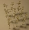
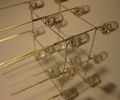
Now repeat this step for the third plane. Attach the second plane from below to the other two, otherwise soldering will not be easy.
That's nearly it! At least the hardest part is done.
|
Now that you've soldered the cube structure, you should continue with Section 3: Assembly and Testing. |
