LED Cube/Understanding The Electronics: Unterschied zwischen den Versionen
Marvin (Diskussion | Beiträge) |
Marvin (Diskussion | Beiträge) Keine Bearbeitungszusammenfassung |
||
| (21 dazwischenliegende Versionen desselben Benutzers werden nicht angezeigt) | |||
| Zeile 1: | Zeile 1: | ||
This page is meant to give you a understanding of the workings in your LED cube. We will try to avoid common electronics slang, thus this is especially suitable for you if you are not familiar with electronics. If you are, however, you are probably better | {{LED Cube Series/en}} | ||
This page is meant to give you a understanding of the workings in your LED cube. We will try to avoid common electronics slang, thus this is especially suitable for you if you are not familiar with electronics. If you are, however, you are probably better off, simply having a look at the schematics and your cube itself - it is not complex in any aspect. | |||
==The Cube Structure== | ==The Cube Structure== | ||
| Zeile 20: | Zeile 21: | ||
[[File:cube-structure-03.png]] | [[File:cube-structure-03.png]] | ||
This is quite a bit more complex. Please take some time | This is quite a bit more complex. Please take some time and look at this diagram. You can clearly see that the "Switch-Resistor-LED" construct has simply been duplicated until we had nine of them. The battery is still only one - we can connect all of these constructs to the same battery. Notice especially that you can already recognize that this is one plane of your cube. The black wires are going downwards, the blue wire is used to connect the short pins of the LEDs together and is then going down separately, using only one wire. Using this pattern and our intelligent switches within our microcontroller we are already able to display two-dimensional patterns. | ||
But, that's not enough! We need two additional planes. The first idea that comes to ones mind may be to again add two copies of that plane, leading to 27 LEDs, 27 Resistors and 27 Switches, and be done. However, this would be quite problematic: One would first of all require a device which has enough switches, is able to bear the current required by the LEDs to light up. Also, we would have a big mess of wires in our cube which will probably not be as nice at one would with their cube to be. So, we are now doing something which is called multiplexing. Don't be scared of this word, it is really easy and we will develop it step by step. | But, that's not enough! We need two additional planes. The first idea that comes to ones mind may be to again add two copies of that plane, leading to 27 LEDs, 27 Resistors and 27 Switches, and be done. However, this would be quite problematic: One would first of all require a device which has enough switches, is able to bear the current required by the LEDs to light up. Also, we would have a big mess of wires in our cube which will probably not be as nice at one would with their cube to be. So, we are now doing something which is called multiplexing. Don't be scared of this word, it is really easy and we will develop it step by step. | ||
First, we simply add additional planes of LEDs, however we connect all LEDs together at the lead to the resistor. Thus, three LEDs share one resistor and one | First, we simply add additional planes of LEDs, however we connect all LEDs together at the lead to the resistor. Thus, three LEDs share one resistor and one switch: | ||
[[File:cube-structure-04.png]] | [[File:cube-structure-04.png]] | ||
But, you see a big, red question mark in this diagram: How | But, you see a big, red question mark in this diagram: How do we connect the opposite wires of the LEDs? Well, we could for example do this: | ||
[[File:cube-structure-05.png]] | [[File:cube-structure-05.png]] | ||
Now, (as you may have already guessed) this is not the best idea. If we now close one switch, the three LEDs that share one resistor and switch will all light up. (Probably only, actually. Something else is possible, but I will not go into it in this document as this would only confuse you.) This is not what we want, as always complete columns would be on. We need a way to disable the other | Now, (as you may have already guessed) this is not the best idea. If we now close one switch, the three LEDs that share one resistor and switch will all light up. (Probably only, actually. Something else is possible, but I will not go into it in this document as this would only confuse you.) This is not what we want, as always complete columns would be on. We need a way to disable the other two LEDs if we only wish to switch on one at a time. And the solution is, you probably guessed it, we add some switches: | ||
[[File:cube-structure-06.png]] | [[File:cube-structure-06.png]] | ||
| Zeile 51: | Zeile 52: | ||
==The Microcontoller and Its Periphery== | ==The Microcontoller and Its Periphery== | ||
[[File:Ucper-01.png|thumb|415px]] | |||
There is not as much to understand about the microcontroller than about the cube. However, there are some things we can show you: | There is not as much to understand about the microcontroller than about the cube. However, there are some things we can show you: | ||
===The Oscillator=== | ===The Oscillator=== | ||
The microcontroller is a | The microcontroller is a synchronous device - and as such it requires a clock. What synchronous means, is actually fairly irrelevant, but implied by the word: Everything happens synchronously - at the same time. This is the reason this clock is required - as a signal when "things" should happen. | ||
The clock for the microcontroller is provided by a crystal. To see how such a crystal works, have a look at [http://www.youtube.com/watch?v=1pM6uD8nePo]. The microcontroller basically excites a device like a tuning fork which then gives it a fairly accurate frequency. (There is much more behind that, but let's leave it at that.) It may be interesting to note that the fork is oscillating at 16 MHz, that are sixteen million oscillations per second. | The clock for the microcontroller is provided by a crystal. To see how such a crystal works, have a look at [http://www.youtube.com/watch?v=1pM6uD8nePo]. The microcontroller basically excites a device like a tuning fork which then gives it a fairly accurate frequency. (There is much more behind that, but let's leave it at that.) It may be interesting to note that the fork is oscillating at 16 MHz, that are sixteen million oscillations per second. | ||
===Decoupling Capacitors=== | |||
On each side of the microcontroller, you find a 100 nF capacitor. The reason for these capacitors also has to do with the synchronousity of the microcontroller: As everything happens at the same time, the energy required at that time is really large compared to the average energy consumption of the microcontroller. Supplying this energy via the long USB cable would not work very good due to many reasons. (To name three: Resistance and Inductance of the USB line and the limited speed of light.) Thus these two capacitors are used to store some energy, which is available when required, directly at the microcontroller. | |||
===Programming Header and Reset Resistor=== | ===Programming Header and Reset Resistor=== | ||
| Zeile 61: | Zeile 66: | ||
The adjacent resistor is called "reset pullup". In normal operation of the microcontroller it will keep the reset pin at "logic high", which is the positive supply voltage. If the reset pin would actually go to "logic low", which is at a much lower voltage, the microcontroller would stop its operation until the pin assumes a "logic high" status. | The adjacent resistor is called "reset pullup". In normal operation of the microcontroller it will keep the reset pin at "logic high", which is the positive supply voltage. If the reset pin would actually go to "logic low", which is at a much lower voltage, the microcontroller would stop its operation until the pin assumes a "logic high" status. | ||
===Bootloader Jumper=== | |||
One very important part is of course the bootloader jumper, which tells the microcontroller to accept an update or to run the old software. It works very much like the reset pin. If at the time of power-on the jumper connects the reset pin to the positive supply voltage, it runs the program. If it connects to the negative supply voltage, the bootloader starts. | |||
===Serial Connector=== | |||
Near the USB sockey, you will find four adjacent pins which don't hold components. These pins are going directly to the microcontroller and can be used for other stuff. Especially interesting should be that you can very easily use this connector to connect to your PC via a USB UART cable. | |||
===Transistor Array=== | ===Transistor Array=== | ||
The aforementioned transistor array, which contains the "blue" switches for the planes is connected to three microcontroller pins. These three pins control which switch is currently closed. | The aforementioned transistor array, which contains the "blue" switches for the planes is connected to three microcontroller pins. These three pins control which switch is currently closed. | ||
=== | ===USB=== | ||
[[File:Ucper-02.png|thumb|300px]] | |||
The USB part is more interesting. We are using the [http://www.obdev.at/products/vusb/index.html V-USB Stack], a very nice, open source USB stack for hobby projects. However, the USB hardware implementation is not much more than a hack. With our LED cube we have quite a problem here: To use the internal switches of the microcontoller, we have to operate it at 5 V. However, the USB data lines do not tolerate much more than 3.3 V. This is the reason for the two diodes directly behind the USB connector: They limit the voltage we get from the microcontroller to acceptable levels. | |||
Then there are three resistors: Two times 68 Ohms are used for the voltage limiting and are "termination resistors". What this means is quite complex to explain, if you do not have some basic background in electronics. Maybe you remember an experiment about waves from your physics classes: If you lay a long rope on the ground and excite it, a wave will traverse this rope. When it reaches the end, it will come back to you! (see [http://www.youtube.com/watch?v=aVCqq5AkePI]) The same thing happens, if you tighten the end of the rope to a fixed object, but this time it is mirrored (see [http://www.youtube.com/watch?v=LTWHxZ6Jvjs]). If you could find something between a loose rope end and a fixed rope end, there will be no reflection. Transmission lines experience a similar behaviour as the rope: The 68 Ohm resistors prevent reflections. | |||
At last there is one 1.5 kOhm resistor. Once a cube is connected to a USB port, one data line will automatically assume nearly the potential of the supply voltage. This is used to signal the USB host that there is a USB device connected on this port. Once the host and the device assume normal operation modes, this resistor has nearly no impact. | |||
Aktuelle Version vom 28. April 2012, 21:16 Uhr
| LED Cube Series | |
|---|---|
|
Chapter 1: Build Section 0: Preparation and Requirements Section 1: PCB Soldering Manual Section 2: Cube Soldering Manual Section 3: Assembly and Testing | |
|
Chapter 2: Play | |
|
Chapter 3: Learn |
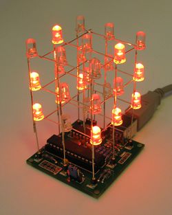
This page is meant to give you a understanding of the workings in your LED cube. We will try to avoid common electronics slang, thus this is especially suitable for you if you are not familiar with electronics. If you are, however, you are probably better off, simply having a look at the schematics and your cube itself - it is not complex in any aspect.
The Cube Structure[Bearbeiten]
We will first explain the cube structure and then work our way to the USB connector. First of all, some basic understanding on how you work with LEDs.
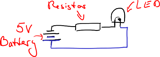
LEDs are very handy and mostly nice-looking devices which is the reason we chose to create this cube kit. Usually, if you connect a LED to a battery, there is a characteristic of the LED you have to take into consideration. For batteries with very low voltage ratings, your LED will not emit light. If you slowly increase the voltage, for example by using different batteries, or, if you are more used to electronics, use a variable voltage source, you will see that at some voltage, current will start to flow through the LED and it lights up. This depends on the color (or the technology) of the LED. Red LEDs for example start to light up at about 1.5 V. However, in contrast to a light bulb, which will not get much brighter or draw much more current at higher voltages, the LED will! Thus, if you want to connect a LED to a commonly available voltage source with a fixed voltage, it is necessary to add a resistor to the circuit which is able to limit this current. So, if you want to connect an LED to a battery, the circuit will look somewhat like this:
Please notice that I have used two colors for the wires: black and blue. You can use these colors to find the same wires in future schematics.
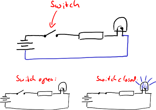
Now, we are not interested to always light up an LED, but we want to be able to switch them off and on to display different patterns on our cube. Thus we add a switch:
With this circuit we can control the LED with the switch. If the switch is closed, the LED lights up. If it is opened, the LED is off. You may have wondered that you do not see this switch on your own LED cube: The switch is included in the microcontroller (the largest device on your board) and controlled by a program that is running on it. Thus you do not have to switch your LED off and on manually, but it is cone automatically.
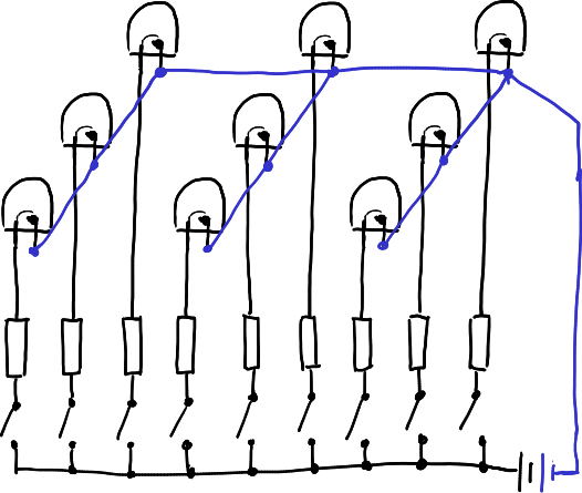
However, we are not nearly done. We do not have only one LED, we have 27 in a 3 * 3 * 3 cube! So, let's add further LEDs to our circuit, which will give us one plane of your cube:
This is quite a bit more complex. Please take some time and look at this diagram. You can clearly see that the "Switch-Resistor-LED" construct has simply been duplicated until we had nine of them. The battery is still only one - we can connect all of these constructs to the same battery. Notice especially that you can already recognize that this is one plane of your cube. The black wires are going downwards, the blue wire is used to connect the short pins of the LEDs together and is then going down separately, using only one wire. Using this pattern and our intelligent switches within our microcontroller we are already able to display two-dimensional patterns.
But, that's not enough! We need two additional planes. The first idea that comes to ones mind may be to again add two copies of that plane, leading to 27 LEDs, 27 Resistors and 27 Switches, and be done. However, this would be quite problematic: One would first of all require a device which has enough switches, is able to bear the current required by the LEDs to light up. Also, we would have a big mess of wires in our cube which will probably not be as nice at one would with their cube to be. So, we are now doing something which is called multiplexing. Don't be scared of this word, it is really easy and we will develop it step by step.
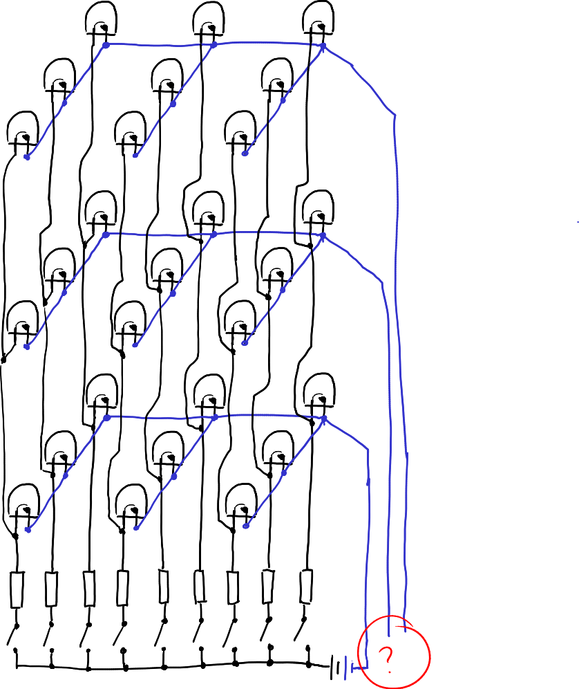
First, we simply add additional planes of LEDs, however we connect all LEDs together at the lead to the resistor. Thus, three LEDs share one resistor and one switch:
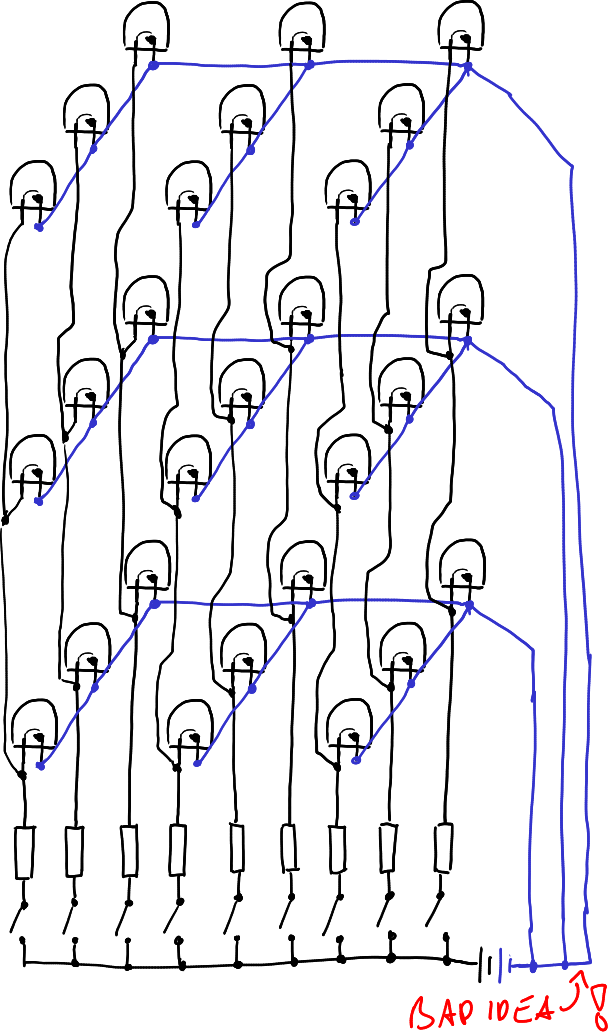
But, you see a big, red question mark in this diagram: How do we connect the opposite wires of the LEDs? Well, we could for example do this:
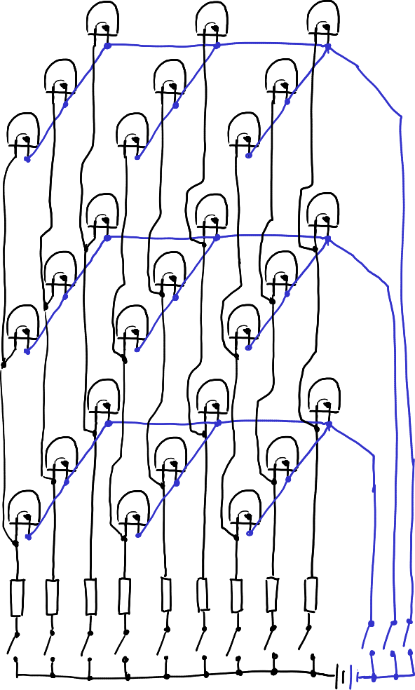
Now, (as you may have already guessed) this is not the best idea. If we now close one switch, the three LEDs that share one resistor and switch will all light up. (Probably only, actually. Something else is possible, but I will not go into it in this document as this would only confuse you.) This is not what we want, as always complete columns would be on. We need a way to disable the other two LEDs if we only wish to switch on one at a time. And the solution is, you probably guessed it, we add some switches:
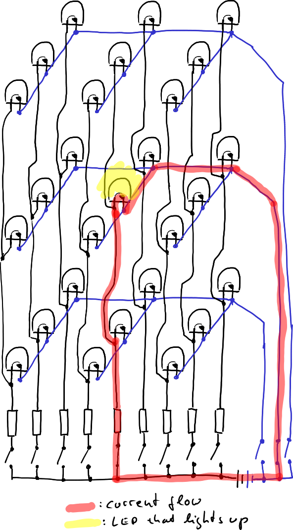
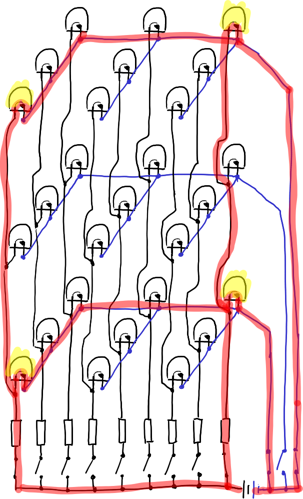
Now we are able to switch on a single LED, for example by switching on one blue and one black switch:
This is nice! We are able to control single LEDs! However, if you want to switch on multiple LEDs we will again hit a bump. If these multiple LEDs are on the same plane, we have no problem. However, if we want to enable LEDs on different planes that are not in the same column, we will experience an effect called ghosting: Two additional LEDs will light up. For example, if we close two switches at opposing edge LEDs we get two additional edge LEDs lighting up:
There is no way to fix this electrically - this is the price you have to pay for multiplexing. However, the cubes are still able to display any pattern you want, even two LEDs of different columns in different planes: The switches we are using are *really* fast, much faster than your eye. Thus the microcontroller will only enable one plane at a time and then show you the image on that plane. Then it will go on to the next plane and display this 2D image and so on. This is then done so fast that you are unable to see it and the cube seems to be illuminated completely all the time.
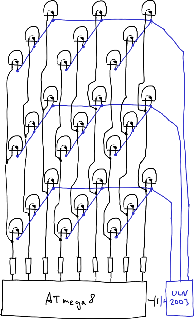
Now, just for completeness: The blue switches are different from the black switches. You will see that the full current of one plane has to be handled by them. Depending on your resistors, this can be quite much for hobby electronics. Also, the microcontoller is not able to handle those currents. Thus, there is a second IC on the board, called "ULN2003". This is simply an array of switches which are able to handle much more current. Thus, the circuit actually looks somewhat like this:
The Microcontoller and Its Periphery[Bearbeiten]
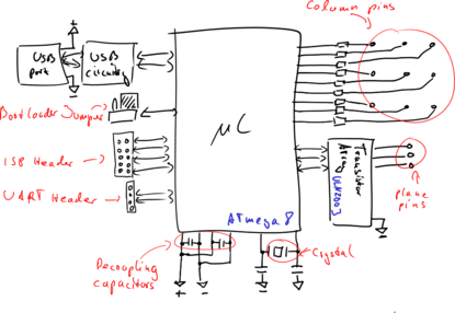
There is not as much to understand about the microcontroller than about the cube. However, there are some things we can show you:
The Oscillator[Bearbeiten]
The microcontroller is a synchronous device - and as such it requires a clock. What synchronous means, is actually fairly irrelevant, but implied by the word: Everything happens synchronously - at the same time. This is the reason this clock is required - as a signal when "things" should happen.
The clock for the microcontroller is provided by a crystal. To see how such a crystal works, have a look at [1]. The microcontroller basically excites a device like a tuning fork which then gives it a fairly accurate frequency. (There is much more behind that, but let's leave it at that.) It may be interesting to note that the fork is oscillating at 16 MHz, that are sixteen million oscillations per second.
Decoupling Capacitors[Bearbeiten]
On each side of the microcontroller, you find a 100 nF capacitor. The reason for these capacitors also has to do with the synchronousity of the microcontroller: As everything happens at the same time, the energy required at that time is really large compared to the average energy consumption of the microcontroller. Supplying this energy via the long USB cable would not work very good due to many reasons. (To name three: Resistance and Inductance of the USB line and the limited speed of light.) Thus these two capacitors are used to store some energy, which is available when required, directly at the microcontroller.
Programming Header and Reset Resistor[Bearbeiten]
You have probably noticed the big unpopulated 2 * 5 pin area on your board with an adjacent 10 kOhm resistor. This header can be used to upload new programs (which you can also do via USB) to the microcontroller or connect additional devices to it, like a bigger memory, for example
The adjacent resistor is called "reset pullup". In normal operation of the microcontroller it will keep the reset pin at "logic high", which is the positive supply voltage. If the reset pin would actually go to "logic low", which is at a much lower voltage, the microcontroller would stop its operation until the pin assumes a "logic high" status.
Bootloader Jumper[Bearbeiten]
One very important part is of course the bootloader jumper, which tells the microcontroller to accept an update or to run the old software. It works very much like the reset pin. If at the time of power-on the jumper connects the reset pin to the positive supply voltage, it runs the program. If it connects to the negative supply voltage, the bootloader starts.
Serial Connector[Bearbeiten]
Near the USB sockey, you will find four adjacent pins which don't hold components. These pins are going directly to the microcontroller and can be used for other stuff. Especially interesting should be that you can very easily use this connector to connect to your PC via a USB UART cable.
Transistor Array[Bearbeiten]
The aforementioned transistor array, which contains the "blue" switches for the planes is connected to three microcontroller pins. These three pins control which switch is currently closed.
USB[Bearbeiten]
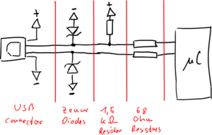
The USB part is more interesting. We are using the V-USB Stack, a very nice, open source USB stack for hobby projects. However, the USB hardware implementation is not much more than a hack. With our LED cube we have quite a problem here: To use the internal switches of the microcontoller, we have to operate it at 5 V. However, the USB data lines do not tolerate much more than 3.3 V. This is the reason for the two diodes directly behind the USB connector: They limit the voltage we get from the microcontroller to acceptable levels.
Then there are three resistors: Two times 68 Ohms are used for the voltage limiting and are "termination resistors". What this means is quite complex to explain, if you do not have some basic background in electronics. Maybe you remember an experiment about waves from your physics classes: If you lay a long rope on the ground and excite it, a wave will traverse this rope. When it reaches the end, it will come back to you! (see [2]) The same thing happens, if you tighten the end of the rope to a fixed object, but this time it is mirrored (see [3]). If you could find something between a loose rope end and a fixed rope end, there will be no reflection. Transmission lines experience a similar behaviour as the rope: The 68 Ohm resistors prevent reflections.
At last there is one 1.5 kOhm resistor. Once a cube is connected to a USB port, one data line will automatically assume nearly the potential of the supply voltage. This is used to signal the USB host that there is a USB device connected on this port. Once the host and the device assume normal operation modes, this resistor has nearly no impact.
