LED Cube/Column Resistors in Detail
Introduction[Bearbeiten]
Choosing the right column resistors for your LED cube requires you to consider several factors:
- Suitability of the cube base for different colors
- Expected USB voltage
- Voltage drop on the microcontroller
- Voltage drop on the transistor array
- Voltage drop on the LED
This page will only cover some basics on how to do these calculations for your own requirements. If you are only building an LED Cube you should refer to the values given in the construction manual.
For now, we are only interested in the resistor value for one specific LED color (and also only one type as a color may be created using different techniques which results in different forward voltages), thus only one LED forward voltage has to be taken into consideration. Also we assume that the USB voltage is 5.0 Volts which is okay, as we will see. Now we are at a situation where we have five volts which will be divided onto our components. Also, we are going to make this calculation only for 20 mA current per LED, however, you can make your own calculations quite easily. Let's have a look at the different I/V characteristics:
Parameters[Bearbeiten]
uC[Bearbeiten]
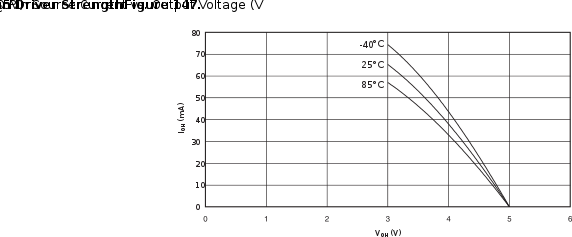
This is a snippet from the ATmega8/L datasheet:
You can clearly see the dropout voltage. In our example with 20 mA current, we have a dropout of 0.5 V.
LED[Bearbeiten]
Dropout voltages for LEDs are somewhat more complex. Ranges can be found at Wikipedia. Commonly used values are:
| Color | Forward Voltage |
|---|---|
| Red | 1.9 |
| Blue | 3.0 |
| Green | 3.0 |
However, they do not only depend on the color, but also on the used technology. Thus it is a good idea to measure the forward voltage of your LEDs before you continue. (One might add that, specifically with cheap LEDs, even the LEDs within the same bag may have a very wide forward voltage range.)
For the sake of an example we will proceed with the 1.9 V drop for the red LED.
Transistor Array[Bearbeiten]
The forward voltage drop in the transistor array is a little bit more tricky and shown in the following curve:
 This is a little bit annoying. Depending on how many LEDs we switch on, the voltage drop changes. For only one LED we have a voltage drop of about 0.7 V. For 9 LEDs we are already at 1 V. We will continue to calculate with the 0.7 V figure as we are interested in bright LEDs for now and we do not want to risk the increased current that will be the result of a reduced voltage drop.
Resistor[Bearbeiten]
Now, we are finally able to calculate our resistor value. This is simply done by subtracting all dropout voltages from the supply voltage and then apply U = R * I. So:
R = (Vcc - Vio - Vta - Vled)/I
  = (5.0 V - 0.5 V - 0.7 V - 1.9 V)/(20 mA)
  = 1.9 V / 20 mA
  = 95 Ohm
Of course, we do not need to use the full 20 mA, which are quite on the limit for the used components. A more reasonable value would be 15 mA:
R = (Vcc - Vio - Vta - Vled)/I
  = 1.9 V / 15 mA
  = 127 Ohm
or 10 mA:
R = (Vcc - Vio - Vta - Vled)/I
  = 1.9 V / 10 mA
  = 190 Ohm
For a blue LED (3.0 V drop) at 10 mA we get:
R = (Vcc - Vio - Vta - Vled)/I
  = (5.0 V - 0.5 V - 0.7 V - 3.0 V)/(10 mA)
  = 0.8 V / 10 mA
  = 80 Ohm
Here is something interesting. We could also calculate with 20 mA:
R = (Vcc - Vio - Vta - Vled)/I
  = (5.0 V - 0.5 V - 0.7 V - 3.0 V)/(20 mA)
  = 0.8 V / 20 mA
  = 40 Ohm
But now let's assume that the USB voltage increased to 5.5 V for whatever reason, which is well within specs. If we assume that this will result in a voltage increase of 0.3 V at the resistor, our current is now 28 mA. For 9 enabled LEDs and the supply current of 20 mA for the uC, this results in a current through the Vcc pins of 268 mA, which is relatively close to the absolute maximum ratings of 300 mA.
Conclusion[Bearbeiten]
We can see that it is quite easy to calculate a useful resistor value for one situation if all parameters are available. However, finding a good balance between brightness (which is perceived proportionally to the logarithm of the current) and a good operating range has to be considered for each situation.
