LED Cube/Zusammensetzen und testen
| LED Cube-Serie | |
|---|---|
|
| |
|
Kapitel 1: Bauen Teil 0: Voraussetzungen & Vorbereitung Teil 1: PCB Lötanleitung Teil 2: Cube Lötanleitung Teil 3: Zusammensetzen und testen | |
|
Kapitel 2: Spielen | |
|
Kapitel 3: Lernen |

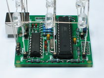
Diese Seite wird dir helfen die Cubestruktur und die Platine zu einem voll funktionsfähigen LED Cube zusammenzusetzen.
Den Cube mit der Platine verbinden
An dieser Stelle solltest Du die Cubeplatine bereits vorbereitet haben. Wenn Du dies noch nicht getan hast, möchtest Du dies vielleicht jetzt tun: LED Cube/PCB Lötanleitung.
Jetzt: Es ist eine gute Idee die Orientierung des Cubes mitzubeachten. Einer der horizontalen Drähte der Ebene ist am weitesten aussen. Welcher das ist kannst Du von diesem Bild erfahren:

In diesem Fall ist es die Seite, die von dir wegzeigt. Versuche diese Seite auf die gleiche Seite zu bringen, auf die auch der USB-Anschluss auf der Platine ist. Es wird dann folgendermaßen aussehen:


An dieser Stelle hast Du bereits die Wahl getroffen, ob Du Anschlüsse für den Cube haben möchtest, oder nicht. Wenn Du keine Anschlüsse verwendest, löte den Cube einfach auf der Platine fest. Wenn Du Anschlüsse verwendest, möchtest Du den Cube jezt dort hineinstecken, oder Du liest was wir dazu zu sagen haben:
Es kann sehr lästig sein, den Cube mit der Platine zu verbinden. Dies hängt davon ab, wie sauber deine Cubestruktur gebastelt wurde. Wir empfehlen die folgende Prozedur:
-
Stecke die drei Beine auf einer Seite des Cubes in ihre Anschlüsse. Stelle sicher, dass sie wirklich drinstecken. Dies kannst Du machen, indem Du den Cube am Konstrukt anhebst: Wenn es schon in der Lage ist die Platine zu halten, ist alles in Ordnung. Klappt es noch nicht, möchtest Du vielleicht eine Kneifzangen verwenden, um sehr vorsichtig Druck auf die unteren LEDs auszuüben.
-
-
Nun hebe vorsichtig die Beine der adjazenten Reihe an und stecke sie in ihre Anschlüsse - aber stecke sie nicht komplett hinein, wie Du es mit der vorherigen Reihe gemacht hast. Dadurch sollte die letzte Reihe nun über ihren Anschlüssen schweben.
-
-
Nun stecke vorsichtig die Beine der mittleren Reihe komplett rein, eins nach dem anderen. Wärend Du dies machst, stelle sicher dass auch die Beine der letzten Reihe in ihre Anschlüsse gleiten. Sie werden wieder nicht komplett hineinreichen. Nachdem alle Anschlüsse der mittleren Reihe fertig sind, stecke die Anschlüsse der letzten Reihe komplett rein. Der Cube sollte an allen Anschlüssen feststecken:
-


Die Ebenenanschlüsse hinzufügen
Jetzt wissen wir, wie der Cube auf der Platine positioniert wird. Als letzten Schritt löten wir die Anschlüsse für die Ebenen fest. Wie Du dich vielleicht erinnerst sind die Drähte die die Ebene
- the wires that are currently holding the planes together are not yet connected to the PCB. To fix this, get some (silver enameled copper) wire. Turn the LED cube, so you look directly onto the USB connector. Then cut one so it is at least long enough to reach from the PCB to the top plane.


Stecke dieses Stück Draht in den rechtesten freien Anschluss von CONN12, wenn Du Anschlüsse verwendest, oder verlöte es auf der Platine am gleichen Platz, wenn nicht. Bieg den Draht so, dass er die obere Ebene berührt und löte die Stelle zusammen:

Widerhole diesen Schritt für den mittleren Pin des Anschlusses und die mittlere Ebene und für den linken Pin und die unterste Ebene:

Inserting the Microcontroller
Get the microcontroller and make sure the leads are bent like the ones of the transistor array. Put it into the socket, taking care that the two notches align.
-
the microcontroller
-
correctly bent legs
-
microcontroller inserted into the socket


Optical Inspection
It is now time to inspect your cube for any shorts. Depending on your testing equipment, you should do this more or less thoroughly, but it is always a good idea. Get a magnifier if your eyes are too bad for it.
Programming the Bootloader
|
If you are taking part in a cccgoe workshop or bought a kit with a pre-flashed microcontroller, skip this step! |
If you do not have a pre-flashed microcontroller, you should now either
- add the ISP header to the PCB and we will flash the bootloader later or
- flash the microcontroller outside of the PCB.
Do whatever you like.
Test Setup
|
If you are at a cccgoe workshop, you can (or should) replace this section by going to one of the tutors. He will do the testing with you and (if he is in a good mood) explain to you what exactly he is doing. |
Now comes the exciting part. We will test if you did everything wrong. This section is divided into several sections. Please pick the one you can perform. The tests are ordered in the following way: Try to do the one on the top. If you do not have the equipment for this, skip to the next test below that and so on. If you have completed one test, you may skip all tests below that one.
Before starting any test, make sure the bootloader jumper is in the following position:

|
Please Note: The device you created is your own. We can not accept responsibility for any defects this causes to your USB Host, Hub or any other Device on the same bus. If you are unsure whether to take any risks, do not take them! |
Test 1: Laboratory Power Supply and USB Isolator
This is the safest test described here. It is also the test that will be performed at cccgoe workshops. You need
- A USB Isolator capable of USB 1.1,
- a Laboratory Power Supply and
- a way to connect the power supply to your isolator.
Now connect your assembled LED Cube to the A port of your isolator. Set the isolator to low speed mode (if necessary). Connect the computer you want to test the device with to the B port of your isolator.
Turn on the laboratory power supply, make sure the outputs are turned off. Tet the current limit to about 40 mA. Set the voltage limit to 5 V. Connect the power supply output to the isolator.
The test starts once you enable the power supply. You should skip to #Test Evaluation before you start it.
Test 2: Laboratory Power Supply and USB Hub
If you only have a laboratory power supply, you have to take a USB cable, you have to find a way to inject this as the power supply voltage. To do so, get a USB cable and carefully cut away the outer plastic isolation layer for a length of about 2 cm near the B connector. Fiddle away the shield, but do not cut it completely. Get the black and the red wire, cut them near the host side of your opening in the cable. You can now connect your power supply to these cables.
Set up the power supply as in Test 1. The test starts once you enable the output, but first go to #Test Evaluation to read about how to evaluate the results.
Test 3: A POWERED USB Hub
This is probably the easiest test, but it may cost you a USB hub or a USB hub power supply. This severely lowers the risk of damaging your computer in contrast to connecting it directly. Simply connect a hub to your computer and supply power to your hub using a separate mains adapter. The test begins once you connect the your LED Cube to your USB hub. However, first go to #Test Evaluation and learn how you can evaluate the results.
Test 4: On an Old Computer, If Nobody Will Care If It Breaks
You can also us an old computer, if it does not matter if it breaks. The test starts once you connect the LED Cube to the computer. However, first read #Test Evaluation to understand how to interpret the results.
Test 5: On a New Computer
Don't. Get at least a USB Hub. Really. This is no joke. However, in general it should be possible. But you know how unforgiving USB hardware is and though it should not damage your computer, it probably will.
Test Evaluation
If the current consumption stays within the 40 mA, the computer didn't turn off and none of the mains adapters blew, nothing catastrophic happened - probably.
|
If you do not have a pre-flashed microcontroller: Now is the time to connect your In-System Programmer and flash the bootloader onto the microcontroller. You will find how to build the bootloader in LED Cube/Building From Source. |
You should now be able to see a line in your kernel log that looks like this:
[158825.185016] generic-usb 0003:16C0:05DF.000E: hiddev0,hidraw0: USB HID v1.01 Device [obdev.at HIDBoot] on usb-0000:00:1d.0-1.1.4.3/input0
The windows users amongst you should get a notification about a new USB device, but not be asked to install drivers.
|
If you did not have a pre-flashed microcontroller: You have to use bootloadHID to add a firmware to your cube to fully test it. |
Those of you who have a laboratory power supply with current limiting, should now increase their current limit to 200 mA.
Now remove the bootloader jumper. The default firmware for all microcontrollers is a firmware that turns on every single LED. You can have a look at the reference cube performing this animation here: (youtube).
|
Well, you've finished building your cube. Now it's time to play with it. However, you should continue reading the usage manual first. |