TVBGone/en

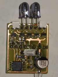
This is a clone of the normal TVBGone Kit. TVBGone is a board that tries to switch off every TV device. This one is built with almost only SMD parts, this board is smaller than the original.
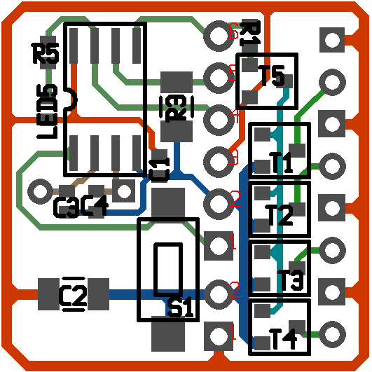
PCB[Bearbeiten]
P1:
1 - Reset
2 - GND
3 - Vcc
4 - SCK
5 - MISO
6 - MOSI
P2:
1 - Vcc
2 - GND
BOM[Bearbeiten]
Necessary[Bearbeiten]
| Designator | Value | Part-No | Price / EUR | Count | Sum / EUR |
|---|---|---|---|---|---|
| R1 | 1 kΩ, 0805 | R: | 0.01 | 1 | 0.01 |
| R3 | 10 kΩ, 1206 | R: | 0.01 | 1 | 0.01 |
| R5 | 470 Ω, 0603 | R: | 0.01 | 1 | 0.01 |
| C1 | 100nF, 0603 | C: | 0.01 | 1 | 0.01 |
| C2 | 100uF | 100uF,1206 | 0.34 | 1 | 0.34 |
| C3, C4 | 22pF 0603 | C: | 0.01 | 2 | 0.02 |
| T1-T4 | NPN SOT23 | BC817 | 0.04 | 4 | 0.16 |
| T5 | PNP SOT23 | BC807 | 0.04 | 1 | 0.04 |
| XTAL1 | 8Mhz hc49 | Q 8 MHZ HC 49/US-SMD | 0.26 | 1 | 0.26 |
| LED5 | yellow 0603 | 0.01 | 1 | 0.01 | |
| uC | SOIC | ATTINY85V-10SU | 1.95 | 1 | 1.95 |
| P1, P2 | 6 Pol, 2 Pole | 0.24 | 1 | 0.24 | |
| S1 | switch | ? | 1 | ? | |
| Sum | 2.86 | ||||
Infrared LEDs[Bearbeiten]
The perfect LEDs aren't found till now. The SMD LEDs have a too big opening angle, so the power is not enough for switching the TV off. On the other hand with 10° you have to target very perfectly... Another problem is that the board haas a bug for the SMD LEDs, if these are solded, they can create a short circuit, but this will be fixed for the next version.
| Designator | Value | Part-No | Price / EUR | Count | Sum / EUR |
|---|---|---|---|---|---|
| LED1 - LED4 | side LED 950nm,60° | Q65110A2463 | 0.35 | 4 | 1.40 |
| LED1 - LED4 | 5 mm, 950 nm, 10° | Q62703Q1820 | 0.27 | 4 | 1.08 |
Battary Connector[Bearbeiten]
| Designator | Value | Part-No | Price / EUR | Count | Sum / EU |
|---|---|---|---|---|---|
| P2 | Batterypack | Vorlage:Pollin | 0.25 | 1 | 0.25 |
| Batteryclip | Vorlage:Pollin | 0.15 | 1 | 0.15 |
Tutorial[Bearbeiten]
Part I[Bearbeiten]
- Start soldering with the uC (ATTINY85V)
- C3 and C4 both 22pF,0603
- Go on with R3(1 kΩ, 0805) and C1(100nF,0603)
- With soldering the plug connector and the Batteryclip you ended this part - Mind the polarity of the battery clip!
- XTAL1 (8 MHz, on the other side)
Part II - Programming[Bearbeiten]
All parts are on the PCB - now start with programming the board.
- download the firmware v1.2 from TVBGone/download.html and use a programmer of your choice. The software you need is descibed on this site: AVR Toolchain).
- test for short circuit
- plug in the programmer Port P1
- change in the Makefile to the right Programmer/Port:
...
#AVRDUDE_PROGRAMMER = usbtiny
AVRDUDE_PROGRAMMER = usbasp
#AVRDUDE_PROGRAMMER = stk500v2
#AVRDUDE_PORT = com3        # programmer connected to serial device
AVRDUDE_PORT = usb
...
- run make full
Part III[Bearbeiten]
Take the next part of your choice and solder it :) Please mind the polarity of LED5 (for the actual package, the green dot is the cathode)!
Testing[Bearbeiten]
Now you are ready for testing see TVBGone/test.html.
Testing Advanced[Bearbeiten]
Go to your electronic store of your choice and test :)
