LED Flower
PCB
BOM
Necessary
| Designator | Value | Part-No | Price / EUR | Count | Sum / EUR |
|---|---|---|---|---|---|
| R1 | 3.6 kΩ, 1206 | R: | 0.01 | 1 | 0.01 |
| R2 | 2.7 kΩ, 1206 | R: | 0.01 | 1 | 0.01 |
| R3, R4 | 68 Ω, 1%, 1206 | CSD: 10-120068 | 0.01 | 2 | 0.02 |
| R5..R19, R38..R40 | 3.6 kΩ, 1206 | R: | 0.01 | 18 | 0.18 |
| R20..R31 | 100 Ω, 1206 | R: | 0.01 | 12 | 0.12 |
| R32..R37 | 150 Ω, 1206 | R: | 0.01 | 6 | 0.06 |
| B1..B3 | 0 Ω, 1206 | R: | 0.01 | 3 | 0.03 |
| T1..T18 | BC807-25, SOT23 | R: BC 807-25 SMD | 0.04 | 18 | 0.72 |
| C1, C2, C3 | 100 nF, 16 V, 0603 | R: X7R-G0603 100N | 0.05 | 3 | 0.15 |
| C4, C5 | 22 pF, 0603 | R: NPO-G0603 22P | 0.05 | 2 | 0.10 |
| C6 | 10 uF, 10 V, 0805 | R: X5R-G0805 10/16 | 0.07 | 1 | 0.07 |
| C9 | 100 nF, 63 V, 1206 | R: X7R-G1206 100N | 0.05 | 1 | 0.05 |
| D2, D3 | 3.6 V Zener Diode, MiniMELF | R: SMD ZF 3,6 | 0.05 | 2 | 0.10 |
| X1 | 20 MHz | R: 20,0000-HC49U-S | 0.18 | 1 | 0.18 |
| ISP, ADC, PWR | 12-pin break-away connector (from a 36-pin strip) | R: SL 1X36W 2,54 | 0.27 | 1 | 0.27 |
| CONN_USB | USB B connector | R: USB BW | 0.21 | 1 | 0.21 |
| U1 | ATmega88-20AU | R: ATMEGA 88-20 AU | 2.95 | 1 | 2.95 |
| LED1..LED6 | RGB LED | ? | 0.30 | 6 | 1.80 |
| 24 Copper wires | 40 cm copper wire cutoff | R: CUL 500/0,63 | 13.90 | 0.058 | 0.81 |
| Sum | 7.84 | ||||
Version 1: USB Powered
| Designator | Value | Part-No | Price / EUR | Count | Sum / EUR |
|---|---|---|---|---|---|
| L1 | 10 uH, 450 mA, 1210 | CSD: 146-121R010 | 0.22 | 1 | 0.22 |
| U2, C7, C8 | Do not populate | 0.00 | 0 | 0.00 | |
| Sum | 0.22 | ||||
Version 2: Externally powered
| Designator | Value | Part-No | Price / EUR | Count | Sum / EUR |
|---|---|---|---|---|---|
| U2 | LM1117-5.0 | CSD: LM1117DT-5,0V | 0.95 | 1 | 0.95 |
| C7, C8 | 10 uF, 10 V, 0805 | R: X5R-G0805 10/16 | 0.07 | 3 | 0.21 |
| D1 | 1N4001, MELF | R: X7R-G1206 100N | 0.04 | 1 | 0.04 |
| L1 | Do not populate | 0.00 | 0 | 0.00 | |
| Sum | 1.20 | ||||
Option: Button
| Designator | Value | Part-No | Price / EUR | Count | Sum / EUR |
|---|---|---|---|---|---|
| R41 | 3.6 kΩ, 1206 | R: | 0.01 | 1 | 0.01 |
| BTN | Pushbutton | ? | 0.10 | 1 | 0.10 |
| Sum | 0.11 | ||||
Tutorial
Soldering Microcontroller and Basic Parts
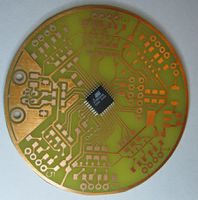
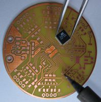
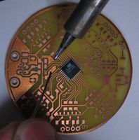
The first step in soldering this board is also the most difficult: Soldering the microcontroller. We are going to use the drag soldering technique. To do so, we first place the microcontroller on the board to get an idea of how it should be placed afterwards. Note the pin one mark which is a small dip in one corner of the IC. This is used to orient it correctly:
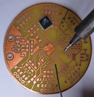
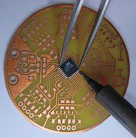
Now remove the microcontroller again, select one pad of the pcb and tin it:
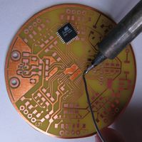
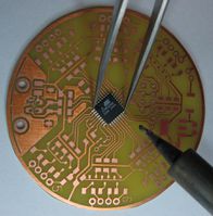
Now grab the microcontroller with a pair of tweezers, heat up the tinned pad and place the microcontroller correctly. Do not overheat the microcontroller: If you are not able to position the microcontroller within about 10 seconds remove the soldering iron and try again after waiting a short amount of time.
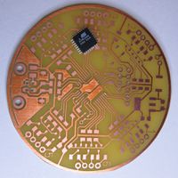
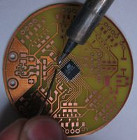
To further secure it, also solder one pin on the opposite corner.
