LED Flower: Unterschied zwischen den Versionen
Marvin (Diskussion | Beiträge) |
Marvin (Diskussion | Beiträge) |
||
| Zeile 588: | Zeile 588: | ||
</gallery> | </gallery> | ||
===The LEDs=== | ===Part II: The LEDs=== | ||
<gallery widths=200px heights=200px perrow=3> | <gallery widths=200px heights=200px perrow=3> | ||
Datei:lf-0300-00.jpeg | Datei:lf-0300-00.jpeg | ||
Version vom 26. Dezember 2010, 00:06 Uhr
PCB


BOM
Necessary
| Designator | Value | Part-No | Price / EUR | Count | Sum / EUR |
|---|---|---|---|---|---|
| R1 | 3.6 kΩ, 1206 | R: | 0.01 | 1 | 0.01 |
| R2 | 2.7 kΩ, 1206 | R: | 0.01 | 1 | 0.01 |
| R3, R4 | 68 Ω, 1%, 1206 | CSD: 10-120068 | 0.01 | 2 | 0.02 |
| R5..R19, R38..R40 | 3.6 kΩ, 1206 | R: | 0.01 | 18 | 0.18 |
| R20..R31 | 100 Ω, 1206 | R: | 0.01 | 12 | 0.12 |
| R32..R37 | 150 Ω, 1206 | R: | 0.01 | 6 | 0.06 |
| B1..B3 | 0 Ω, 1206 | R: | 0.01 | 3 | 0.03 |
| T1..T18 | BC807-25, SOT23 | R: BC 807-25 SMD | 0.04 | 18 | 0.72 |
| C1, C2, C3 | 100 nF, 16 V, 0603 | R: X7R-G0603 100N | 0.05 | 3 | 0.15 |
| C4, C5 | 22 pF, 0603 | R: NPO-G0603 22P | 0.05 | 2 | 0.10 |
| C6 | 10 uF, 10 V, 0805 | R: X5R-G0805 10/16 | 0.07 | 1 | 0.07 |
| C9 | 100 nF, 63 V, 1206 | R: X7R-G1206 100N | 0.05 | 1 | 0.05 |
| D2, D3 | 3.6 V Zener Diode, MiniMELF | R: SMD ZF 3,6 | 0.05 | 2 | 0.10 |
| X1 | 20 MHz | R: 20,0000-HC49U-S | 0.18 | 1 | 0.18 |
| ISP, ADC, PWR | 12-pin break-away connector (from a 36-pin strip) | R: SL 1X36W 2,54 | 0.27 | 1 | 0.27 |
| CONN_USB | USB B connector | R: USB BW | 0.21 | 1 | 0.21 |
| U1 | ATmega88-20AU | R: ATMEGA 88-20 AU | 2.95 | 1 | 2.95 |
| LED1..LED6 | RGB LED | ? | 0.30 | 6 | 1.80 |
| 24 Copper wires | 40 cm copper wire cutoff | R: CUL 500/0,63 | 13.90 | 0.058 | 0.81 |
| Sum | 7.84 | ||||
Version 1: USB Powered
| Designator | Value | Part-No | Price / EUR | Count | Sum / EUR |
|---|---|---|---|---|---|
| L1 | 10 uH, 450 mA, 1210 | CSD: 146-121R010 | 0.22 | 1 | 0.22 |
| U2, C7, C8 | Do not populate | 0.00 | 0 | 0.00 | |
| Sum | 0.22 | ||||
Version 2: Externally powered
| Designator | Value | Part-No | Price / EUR | Count | Sum / EUR |
|---|---|---|---|---|---|
| U2 | LM1117-5.0 | CSD: LM1117DT-5,0V | 0.95 | 1 | 0.95 |
| C7, C8 | 10 uF, 10 V, 0805 | R: X5R-G0805 10/16 | 0.07 | 2 | 0.14 |
| D1 | 1N4001, MELF | R: X7R-G1206 100N | 0.04 | 1 | 0.04 |
| L1 | Do not populate | 0.00 | 0 | 0.00 | |
| Sum | 1.13 | ||||
Option: Button
| Designator | Value | Part-No | Price / EUR | Count | Sum / EUR |
|---|---|---|---|---|---|
| R41 | 3.6 kΩ, 1206 | R: | 0.01 | 1 | 0.01 |
| BTN | Pushbutton | ? | 0.10 | 1 | 0.10 |
| Sum | 0.11 | ||||
Tutorial
This Tutorial consists of three parts. The first two parts do not necessarily have to be completed in the given order. Also, two people may work simultaneously, each on one part.
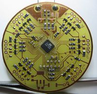
Part I: The PCB
Microcontroller
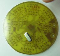
The first step in soldering this board is also the most difficult: Soldering the microcontroller. We are going to use the drag soldering technique. To do so, we first place the microcontroller on the board to get an idea of how it should be placed afterwards. Notice the pin one mark which is a small dip in one corner of the IC. This is used to orient it correctly:

Before proceeding, please read the entire section about soldering the microcontroller and make sure you understood everything. Now remove the microcontroller again, select one pad of the pcb and tin it. For this and the next two steps, you don't have to worry about any solder bridges, we will remove them afterwards.


Now grab the microcontroller with a pair of tweezers, heat up the tinned pad and place the microcontroller correctly. Do not overheat the microcontroller: If you are not able to position the microcontroller within about 10 seconds remove the soldering iron and try again after waiting a short amount of time.


To further secure it, also solder one pin on the opposite corner.


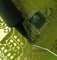
Now select one edge of the microcontroller that has not been used in the previous steps and add some Flux to pins. What comes now is not easy and probably may require multiple attempts: Solder some pins one on side of the edge at once and then just slide the soldering iron slowly and without any pressure to the other side:


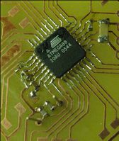
If you have done everything right (right speed, correct amound of solder and flux) all pins will be soldered to the board and there will be no bridges between them:

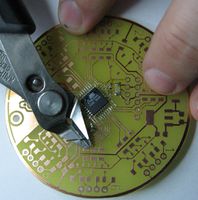
If you have created any bridges, there are two ways to get rid of them:
- Drag the solder away from the microcontroller.
- Use a desoldering gun or desoldering wig.
However, repeat this process for the three other edges that are not yet soldered completely:

Decoupling Capacitors
To operate, the microcontroller needs a set of decoupling capacitors. These are two-padded components, so we will esentially replicate the first steps of the microcontroller soldering process:
- Tin one pad,
- add the component and
- solder the other side.
The first one is C9, a 100 nF capacitor in a 1206 package, the biggest of the capacitors included in this kit:


Now continue with C1 using the same process. C1 is also a 100 nF capacitor, but in a 0603 package.


And now C2 and C3, both the same capacitor as C1.


Crystal Oscillator
Next step is the crystal oscillator. To prepare for that, we will first solder the capacitors C4 and C5 which are both 22 pf 0603 capacitors.


The crystal oscillator then goes directly on the other side of the pcb below those two capacitors. Just put it in and solder both pins.
-
Position of the Crystal
-
From the bottom
-
Solder both pins


Then clip off anything that is above the solder joint.
-
Clip off the excess wire

Programming and Analog Input Headers
Now we add two headers, one for programming the microcontroller, one for the analog input of the microcontroller. Again, the headers are on the back side of the PCB.


Now simply solder each pin to the PCB:


First Test
Get a lab power supply and set the maximum voltage to 5 V and the maximum current to zero. Connect the positive terminal (red) and negative terminal (black) as shown in the picture below:
-
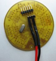
The positive terminal goes to the leftmost pin of the shorter connector, the negative terminal to the middle one of the remaining three pins.

Slowly increase the current. The current should not exceed 20 mA.
If you have reached 20 mA, but the voltage is still below the previously set voltage limit, there is something wrong. Do not further increase the current limit as this could damage the device. Check if every component is soldered and oriented correctly, check if there are any solder bridges.
If everything is okay, connect the in-system programmer. From left to right it's: MOSI, MISO, SCK, Vcc, GND, /RESET

Programming the Microcontroller's Fuses
Go into the source folder, adapt the programmer.mk to use your programmer and execute make fuses:
source$ make fuses
avrdude -c avrispmkII -P usb -B  100 -p m88  -U lfuse:w:0xff:m -U hfuse:w:0xdf:m -U efuse:w:0xf9:m

avrdude: AVR device initialized and ready to accept instructions

Reading | ################################################## | 100% 0.02s

avrdude: Device signature = 0x1e930a
avrdude: reading input file "0xff"
avrdude: writing lfuse (1 bytes):

Writing | ################################################## | 100% 0.01s

avrdude: 1 bytes of lfuse written
avrdude: verifying lfuse memory against 0xff:
avrdude: load data lfuse data from input file 0xff:
avrdude: input file 0xff contains 1 bytes
avrdude: reading on-chip lfuse data:

Reading | ################################################## | 100% 0.00s

avrdude: verifying ...
avrdude: 1 bytes of lfuse verified
avrdude: reading input file "0xdf"
avrdude: writing hfuse (1 bytes):

Writing | ################################################## | 100% 0.00s

avrdude: 1 bytes of hfuse written
avrdude: verifying hfuse memory against 0xdf:
avrdude: load data hfuse data from input file 0xdf:
avrdude: input file 0xdf contains 1 bytes
avrdude: reading on-chip hfuse data:

Reading | ################################################## | 100% 0.00s

avrdude: verifying ...
avrdude: 1 bytes of hfuse verified
avrdude: reading input file "0xf9"
avrdude: writing efuse (1 bytes):

Writing |                                                    | 0% 0.00s ***failed;
Writing | ################################################## | 100% 0.05s

avrdude: 1 bytes of efuse written
avrdude: verifying efuse memory against 0xf9:
avrdude: load data efuse data from input file 0xf9:
avrdude: input file 0xf9 contains 1 bytes
avrdude: reading on-chip efuse data:

Reading | ################################################## | 100% 0.00s

avrdude: verifying ...
avrdude: verification error, first mismatch at byte 0x0000
         0xf9 != 0x01
avrdude: verification error; content mismatch

avrdude: safemode: efuse changed! Was f9, and is now 1
Would you like this fuse to be changed back? [y/n] n
avrdude: safemode: Fuses OK

avrdude done.  Thank you.

make: *** [fuses] Error 1
If you are asked if you want to change back the efuse as it has not been written correctly, just say 'n'. In fact the fuse has probably been written correctly, the upper bits are just not writable and always remain 1.
To program the microcontroller and check if the oscillator is working, just execute make:
source$ make
Building objects  build/base.o  build/usb.o  build/leds.o  build/usbdrv/usbdrv.o  build/usbdrv/oddebug.o  build/usbdrv/usbdrvasm.o -> build/out.elf -> build/out.hex
make build/out.hex
make[1]: Entering directory `source'
avr-gcc -std=gnu99  -W -Wall -pedantic -DF_CPU=20000000UL -mmcu=atmega88 -O2 -ffreestanding -Wl,--relax   -c src/base.c -o build/base.o
avr-gcc -std=gnu99  -W -Wall -pedantic -DF_CPU=20000000UL -mmcu=atmega88 -O2 -ffreestanding -Wl,--relax   -c src/usb.c -o build/usb.o
avr-gcc -std=gnu99  -W -Wall -pedantic -DF_CPU=20000000UL -mmcu=atmega88 -O2 -ffreestanding -Wl,--relax   -c src/leds.c -o build/leds.o
avr-gcc -std=gnu99  -W -Wall -pedantic -DF_CPU=20000000UL -mmcu=atmega88 -O2 -ffreestanding -Wl,--relax   -c src/usbdrv/usbdrv.c -o build/usbdrv/usbdrv.o
src/usbdrv/usbdrv.c:115: warning: overflow in implicit constant conversion
src/usbdrv/usbdrv.c:154: warning: overflow in implicit constant conversion
src/usbdrv/usbdrv.c:156: warning: overflow in implicit constant conversion
src/usbdrv/usbdrv.c: In function ‘usbHandleResetHook’:
src/usbdrv/usbdrv.c:550: warning: unused parameter ‘notResetState’
avr-gcc -std=gnu99  -W -Wall -pedantic -DF_CPU=20000000UL -mmcu=atmega88 -O2 -ffreestanding -Wl,--relax   -c src/usbdrv/oddebug.c -o build/usbdrv/oddebug.o
avr-gcc -std=gnu99  -W -Wall -pedantic -DF_CPU=20000000UL -mmcu=atmega88 -O2 -ffreestanding -Wl,--relax   -c src/usbdrv/usbdrvasm.S -o build/usbdrv/usbdrvasm.o
avr-gcc -std=gnu99  -W -Wall -pedantic -DF_CPU=20000000UL -mmcu=atmega88 -O2 -ffreestanding -Wl,--relax    build/base.o  build/usb.o  build/leds.o  build/usbdrv/usbdrv.o  build/usbdrv/oddebug.o  build/usbdrv/usbdrvasm.o -o build/out.elf
avr-size build/out.elf
   text	   data	    bss	    dec	    hex	filename
   1862	      2	     65	   1929	    789	build/out.elf
avr-objcopy -R .eeprom -O ihex -v build/out.elf build/out.hex
copy from `build/out.elf' [elf32-avr] to `build/out.hex' [ihex]
make[1]: Leaving directory `source'
make flash
make[1]: Entering directory `source'
avrdude -c avrispmkII -P usb -B  1 -p m88  -U flash:w:build/out.hex:i

avrdude: AVR device initialized and ready to accept instructions

Reading | ################################################## | 100% 0.00s

avrdude: Device signature = 0x1e930a
avrdude: NOTE: FLASH memory has been specified, an erase cycle will be performed
         To disable this feature, specify the -D option.
avrdude: erasing chip
avrdude: reading input file "build/out.hex"
avrdude: writing flash (1864 bytes):

Writing | ################################################## | 100% 0.20s

avrdude: 1864 bytes of flash written
avrdude: verifying flash memory against build/out.hex:
avrdude: load data flash data from input file build/out.hex:
avrdude: input file build/out.hex contains 1864 bytes
avrdude: reading on-chip flash data:

Reading | ################################################## | 100% 0.10s

avrdude: verifying ...
avrdude: 1864 bytes of flash verified

avrdude: safemode: Fuses OK

avrdude done.  Thank you.

make[1]: Leaving directory `source'
USB Port
Solder R2, R3, R4, D2, D3 and the USB connector as shown below.


Testing the USB Port
Let's test the USB port. However, note that this port does not follow the USB specifications and could damage your computer. There are at least two ways to prevent this: 1. First connect the device to a hub that is not connected to the Host and see what happens. Then connect your Host to the Hub. 2. Even better would be to add a USB isolator as the one used below.

After connecting the Device to your Host, you should get a notification about a new USB device:
trottel kernel: [76212.960126] usb 1-4.3.2: new low speed USB device using ehci_hcd and address 59
When you see this line, the tricky part of this Workshop is done.
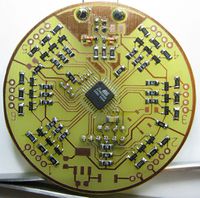
Finishing the PCB's Core
Just to improve some electromagnetic emissions, add bridges (or 0 Ohm Resistors) B1, B2 and B3.

Base & Reset Resistors
Now we are going to add the /Reset pullup resistor R1 and base resistors R8 to R19 and R38 to R40 with 3.6 kΩ resistors

Transistors
Now we are adding the transistors T1 to T18 (BC807).


LED Resistors
Next are the resistors that limit the current flow through the LEDs. If you are using the parts supplied at the 27C3 Peace Mission in Goettingen, you can just use the values given here. If you are using other LEDs, please calculate your own Values. First are the 150 Ω resistors R20 to R25 for the red LEDs. Then the 150 Ω resistors R26 to R31 for the green and R32 to R37 for the blue LEDs are following:
-
The red resistors...
-
...and red, green and blue.


Optional: USB Power Supply
One way to supply the device is to use USB power. However, you should note that if you choose this option, you are not able to plug in the external power supply while the device is connected to USB. Also, the device may not conform to the USB specification in terms of power limitations.
To activate the USB power supply, just solder the 10 uH coil to L1 and a 10 uF capacitor to C6:


Optional: Voltage Regulator for external Supply
Instead of using the USB power supply, you can also add an external supply, for example a 9V battery. Do not use USB power supply and the external voltage regulator simultaneously!
To use this supply, add a two pin connector as shown below:


Then add a 1N400x diode to D1, an LM1117 (or AMS1117 in this case) to U2 and 10 uF, 10V capacitors to C7 and C8:


