LED Cube/Zusammensetzen und testen: Unterschied zwischen den Versionen
Marvin (Diskussion | Beiträge) (Die Seite wurde neu angelegt: „{{LED Cube Series}} This page helps you to assemble cube structure and PCB to the fully functional LED Cube. ==Connecting the Cube to Your PCB== You should …“) |
Marvin (Diskussion | Beiträge) Keine Bearbeitungszusammenfassung |
||
| Zeile 1: | Zeile 1: | ||
{{LED Cube Series}} | {{LED Cube Series/de}} | ||
This page helps you to assemble cube structure and PCB to the fully functional [[LED Cube]]. | This page helps you to assemble cube structure and PCB to the fully functional [[LED Cube]]. | ||
Version vom 28. April 2012, 21:19 Uhr
| LED Cube-Serie | |
|---|---|
|
Kapitel 1: Bauen Teil 0: Voraussetzungen & Vorbereitung Teil 1: PCB Lötanleitung Teil 2: Cube Lötanleitung Teil 3: Zusammensetzen und testen | |
|
Kapitel 2: Spielen | |
|
Kapitel 3: Lernen |
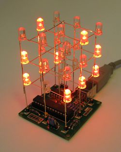
This page helps you to assemble cube structure and PCB to the fully functional LED Cube.
Connecting the Cube to Your PCB
You should have already prepared the LED Cube PCB prior to the cube structure. If not, you probably want to do this now: LED Cube/PCB Soldering Manual.
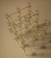
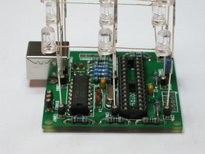
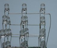
Now: It may be a good idea to take the orientation of this cube into consideration. One of the horizontal wires of the planes is most outside. You can tell this from this picture:
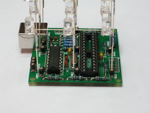
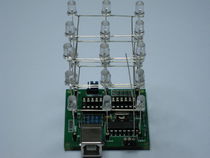
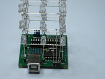
In this case, it is the side pointing away from you. Try to get this side on the same side as the USB connector on the PCB. It will then look like this:
Now, you already made your choice if you wanted to use connectors for the cube or not. If you are not using connectors, simply solder your cube to the PCB. If you are using connectors you may plug your cube in now or read what we have to say about this:
Connecting the cube to the pcb may be quite tedious, depending on the accuracy of your cube structure. We suggest you follow this procedure:
-
Plug the three legs on one side of the cube into their connectors. Make sure they are really plugged in. Maybe you have to use some pliers or extremely carefully apply pressure to the bottom LED. You can do this by lifting up your construction at the cube: If it is already able to lift up the PCB, everything is okay.
-
-
Now carefully lift up the legs in the adjacent row and put them into their connectors - but don't plug them in completely as you did with the previous row. This should leave the last row floating above their connectors.
-
-
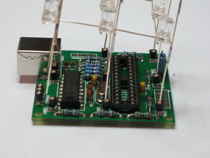
Now carefully insert the legs of the center row completely, one by one. While doing this, make sure that the connectors of the last row are sliding into their connectors, too. They will however, as already mentioned above, not completely enter the connectors. After you inserted all connectors of the center row, completely plug in the connectors of the last row. The cube should then be plugged into all connectors:
-
Adding the Plane Connectors
Now we know how the cube is positioned on the PCB. The final soldering step is to add the connectors for the planes. If you remember - the wires that are currently holding the planes together are not yet connected to the PCB. To fix this, get some (silver enameled copper) wire. Turn the LED cube, so you look directly onto the USB connector. Then cut one so it is at least long enough to reach from the PCB to the top plane.
Plug this piece of wire into the rightmost free connector of CONN12, if you are using connectors, or solder it into the PCB at the same place, if not. Bend the wire so that it touches the top plane and solder them together:
Repeat this step for the center pin of the connector and the plane in the middle and the leftmost pin of the connector and the bottom plane:
