LED Cube/Cube Lötanleitung: Unterschied zwischen den Versionen
| Zeile 21: | Zeile 21: | ||
</gallery> | </gallery> | ||
== | ==Das Biegen der LEDs== | ||
Im zweiten Schritt müssen wir die Beine der LEDs so biegen, dass sie ohne viel Materialermüdung zu einem Cube zusammengefügt werden können. Sei vorsichtig mit den nächsten Schritten, denn sie sind dafür entscheidend, wie dein Cube hinterher aussehen wird. Versuch die Biegungen möglichst immer beim ersten Mal richtig zu machen. Wenn Du zu viel an den Beinen rumbiegst, werden sie abbrechen. | |||
=== | ===Kurzes Bein=== | ||
Nimm zunächst eine LED: | |||
<gallery> | <gallery> | ||
File:cs3-004.jpeg | File:cs3-004.jpeg | ||
</gallery> | </gallery> | ||
Halte sie nach unten gerichtet und stelle sicher, dass das längere der beiden Beine das Linke ist und das Kürzere das Rechte. Dann biege das kürzere Bein um 90 Grad in deine Richtung, so dass die LED hinterher wie folgt aussieht: | |||
<gallery> | <gallery> | ||
File:cs3-005.jpeg | File:cs3-005.jpeg | ||
| Zeile 35: | Zeile 35: | ||
</gallery> | </gallery> | ||
Wiederhole diesen Schritt für alle LEDs und überprüfe immer zweimal, ob Du auch gerade das richtige Bein biegst. Verwechselst Du einmal die Beine, wird die entsprechende LED nicht leuchten. | |||
<gallery> | <gallery> | ||
File:cs3-007.jpeg | File:cs3-007.jpeg | ||
</gallery> | </gallery> | ||
=== | ===Langes Bein=== | ||
Wiederhole wieder für alle LEDs den folgenden Schritt: Nimm eine LED und halte sie wie letztes Mal. Dieses Mal ist natürlich das kurze Bei bereits zu dir gebogen. Das lange Bein auf der linken Seite muss nun um 90 Grad nach links gebogen werden. Das Resultat sieht folgendermaßen aus: | |||
<gallery> | <gallery> | ||
File:cs3-008.jpeg | File:cs3-008.jpeg | ||
</gallery> | </gallery> | ||
Nun nimm ein Paar flachnasige Greifzangen und halte das gleiche Bein dort wo der LED-Körper endet: | |||
<gallery> | <gallery> | ||
File:cs3-009.jpeg | File:cs3-009.jpeg | ||
| Zeile 51: | Zeile 51: | ||
</gallery> | </gallery> | ||
Und bieg es nach hinten hoch. Das längere Bein zeigt nun in die gleiche Richtung wie zuvor in diesem Schritt, jedoch um ein Stück von der LED wegversetzt: | |||
<gallery> | <gallery> | ||
File:cs3-011.jpeg | File:cs3-011.jpeg | ||
| Zeile 57: | Zeile 57: | ||
</gallery> | </gallery> | ||
Vergiss nicht diesen Schritt mit jeder LED zu wiederholen: | |||
<gallery> | <gallery> | ||
File:cs3-013.jpeg | File:cs3-013.jpeg | ||
</gallery> | </gallery> | ||
==Assembling the Planes== | ==Assembling the Planes== | ||
We have nearly finished preparing the LEDs. It is now time to assemble the planes. To get to the plane, we will first assemble a single row. A very handy tool for this is a plate with holes drilled into it where the LEDs belong. | We have nearly finished preparing the LEDs. It is now time to assemble the planes. To get to the plane, we will first assemble a single row. A very handy tool for this is a plate with holes drilled into it where the LEDs belong. | ||
Version vom 21. April 2012, 16:30 Uhr
Vorlage:LED Cube Series Diese Seite der LED Cube-Serie gibt Dir eine Anleitung, wie Du die Cubestruktur des LED-Cubes bauen kannst. Die Struktur zu bauen ist nicht sehr schwer, aber kann manchmal frustrieren sein, wenn die Drähte nicht so wollen wie Du. Das ist ganz normal und dein erster Cube wird wahrscheinlich nicht perfekt aussehen. Dafür ist dies ja auch ein Anfängerworkshop, es gibt einiges zu lernen.
LED-Vorbereitung
Wie der erste Schritt aussieht hängt von deinen LEDs ab. In diesem Beispiel werden klare einfarbige LEDs verwendet:
Wenn Du matte LEDs hast, kannst Du diesen Schritt überspringen.
Klare LEDs haben einen großen Vorteil gegenüber Matten: Dadurch dass Du durch sie hindurchsehen kannst wirkt die Illusion von freihängenden Lichtern viel besser. Sie haben aber auch einen Nachteil: Es kommt nur ein sehr schmaler Lichtstrahl aus der Oberseite der LED, da das Licht kaum gestreut wird. Das macht es nahezu unmöglich von oben in sie hineinzugucken und von der Seite scheinen sie fast garnicht. LEDs in den unteren Ebenen des Cubes beleuchten die über ihnen liegenden LEDs. Ein guter Workaround um dieses Problem zu umgehen ist einen Streifen Schmürgelpapier zu nehmen und die Oberseite der LEDs anzurauhen. Hier kannst Du die Unterschiede sehen:
Wiederhole diesen Schritt mit allen LEDs, wenn Du willst. Versuch die Beine dabei nicht zusehr zu verbiegen, denn das würde das Material ermüden und der Cube sieht hinterher durch die Unregelmäßigkeiten nicht mehr so toll aus. (Vielleicht möchtest Du ja auch soeinen Cube haben, das ist deine Entscheidung :) .)
Das Biegen der LEDs
Im zweiten Schritt müssen wir die Beine der LEDs so biegen, dass sie ohne viel Materialermüdung zu einem Cube zusammengefügt werden können. Sei vorsichtig mit den nächsten Schritten, denn sie sind dafür entscheidend, wie dein Cube hinterher aussehen wird. Versuch die Biegungen möglichst immer beim ersten Mal richtig zu machen. Wenn Du zu viel an den Beinen rumbiegst, werden sie abbrechen.
Kurzes Bein
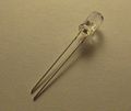
Nimm zunächst eine LED:
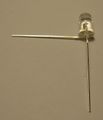
Halte sie nach unten gerichtet und stelle sicher, dass das längere der beiden Beine das Linke ist und das Kürzere das Rechte. Dann biege das kürzere Bein um 90 Grad in deine Richtung, so dass die LED hinterher wie folgt aussieht:
Wiederhole diesen Schritt für alle LEDs und überprüfe immer zweimal, ob Du auch gerade das richtige Bein biegst. Verwechselst Du einmal die Beine, wird die entsprechende LED nicht leuchten.
Langes Bein
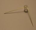
Wiederhole wieder für alle LEDs den folgenden Schritt: Nimm eine LED und halte sie wie letztes Mal. Dieses Mal ist natürlich das kurze Bei bereits zu dir gebogen. Das lange Bein auf der linken Seite muss nun um 90 Grad nach links gebogen werden. Das Resultat sieht folgendermaßen aus:
Nun nimm ein Paar flachnasige Greifzangen und halte das gleiche Bein dort wo der LED-Körper endet:
Und bieg es nach hinten hoch. Das längere Bein zeigt nun in die gleiche Richtung wie zuvor in diesem Schritt, jedoch um ein Stück von der LED wegversetzt:
Vergiss nicht diesen Schritt mit jeder LED zu wiederholen:
Assembling the Planes
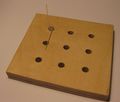
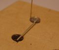
We have nearly finished preparing the LEDs. It is now time to assemble the planes. To get to the plane, we will first assemble a single row. A very handy tool for this is a plate with holes drilled into it where the LEDs belong.
Just insert the first LED into the top left corner of the plate, with the legs oriented like this:
Now cut the horizontal leg at the point where it has completely passed the adjacent hole:
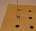
Into the hole that is passed by the leg from the first LED, insert the next LED like this:
Again, cut the leg just after it passed the next hole:
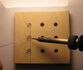
Add the third LED like this and solder the legs together at the second and third LED:
The end result will look like this:
Now cut the leg of the lowest LED directly after the solder joint:
Repeat these steps to create the next two rows:
Take two pieces of (preferably silver-enameled copper) wire that are long enough to fit across the cube:
Solder all three joints of the three wires with the horizontal wires. Make sure these wires do not touch the vertical wires.
Cat away the any excess wire:
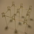
After you removed the construction from the plate you have the first plane ready. Carefully wiggle a bit on the long legs to check if all the solder joints are holding. If they don't, redo them.
Repeat this step for the next two planes so you have three planes before you continue.
Assembling the Cube
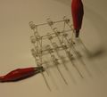
Now you should three have at least somewhat identical planes. The next step is obviously to join them to a cube. It is a good idea to fixiate two planes together, before trying to solder. We do this with alligator clips:
Make sure the planes are oriented the same way, if not, the LEDs will be shifted. Now just solder all nine joints. You may have to bend some wires a bit until they match:
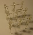
Make sure you soldered all nine joints, especially the middle one. To fix this may be difficult, depending on your cube and tools available. You will get two nicely joined planes:
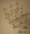
Now repeat this step for the third plane. Attach the second plane from below to the other two, otherwise soldering will not be easy.
That's nearly it! At least the hardest part is done.
Connecting the Cube to Your PCB
You should have already prepared the LED Cube PCB prior to the cube structure. If not, you probably want to do this now: LED Cube/PCB Soldering Manual.
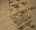
If you are using connectors for the cube structure, go ahead and plug your cube into the nine column connectors. If you do not have connectors, still perform simply put the cube into the PCB and solder it. In both cases: It may be a good idea to take the orientation of this cube into consideration. One of the horizontal wires of the planes is most outside. You can tell this from this picture:
In this case, it is the side pointing away from you.
Try to get this side on the same side as the USB connector on the PCB. This will look like this:
@todo
Adding the Plane Connectors
Now we know how the cube is positioned on the PCB. The final soldering step is to add the connectors for the planes. If you remember - the wires that are currently holding the planes together are not yet connected to the PCB:
@todo pic
To fix this, get some (silver enameled copper) wire. Turn the LED cube, so you look directly onto the USB connector. Then cut one so it is at least long enough to reach from the PCB to the top plane.
@todo pics
Plug this piece of wire into the rightmost free connector of CONN12, if you are using connectors, or solder it into the PCB at the same place, if not. Bend the wire so that it touches the top plane and solder them together:
@todo pics
Repeat this step for the center pin of the connector and the plane in the middle and the leftmost pin of the connector and the bottom plane:
