LED Cube/PCB Soldering Manual: Unterschied zwischen den Versionen
Zur Navigation springen
Zur Suche springen
Marvin (Diskussion | Beiträge) Keine Bearbeitungszusammenfassung |
Marvin (Diskussion | Beiträge) Keine Bearbeitungszusammenfassung |
||
| Zeile 12: | Zeile 12: | ||
|R11||68 Ohm||[[File:r-68.jpeg|frameless|border]] | |R11||68 Ohm||[[File:r-68.jpeg|frameless|border]] | ||
|- | |- | ||
|R13|| | |R13||1500 Ohm||[[File:r-1500.jpeg|frameless|border]] | ||
|} | |} | ||
Version vom 14. April 2012, 21:33 Uhr
A full schematic of the PCB can be downloaded here: Datei:Cube.pdf.
USB Resistors and Zener Diodes

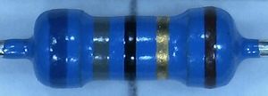
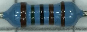
First we solder R10, R11, R13, Z1 and Z2. You can see the resistor values in the schematic or in the table below, together with the color code marking:
| Name | Value | Color Code |
|---|---|---|
| R10 | 68 Ohm | 
|
| R11 | 68 Ohm | 
|
| R13 | 1500 Ohm | 
|