LED Cube/PCB Soldering Manual
| LED Cube Series | |
|---|---|
|
| |
|
Chapter 1: Build Section 0: Preparation and Requirements Section 1: PCB Soldering Manual Section 2: Cube Soldering Manual Section 3: Assembly and Testing | |
|
Chapter 2: Play | |
|
Chapter 3: Learn |

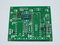
This page contains the soldering manual for the PCB of the LED Cube.
A full schematic of the PCB can be downloaded here: Datei:Cube.pdf.
USB Resistors

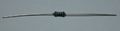
First we solder R10, R11 and R13. As all resistors we are using in this project, their orientation is not relevant. You can see the resistor values in the schematic or in the table below, together with the color code marking:
| Name | Value | Color Code |
|---|---|---|
| R10 | 68 Ohm |  (blue-green-black-gold-brown) (blue-green-black-gold-brown)
|
| R11 | 68 Ohm | (blue-green-black-gold-brown)
|
| R13 | 1500 Ohm |  (brown-green-black-brown-brown) (brown-green-black-brown-brown)
|
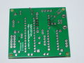
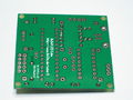
To solder them, first bend both leads about 90 degrees, so they fit into the two holes. The distance between the leads, as with every resistor we will solder on this board, is about 11 mm, but it is not important to be very accurate here. Place them into the holes, flip the PCB and solder them on the back side. Afterwards, clip away any excess wire, but do not damage the solder joint by clipping away more than necessary.
-
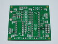
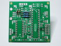
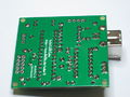
plain PCB
-
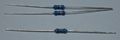
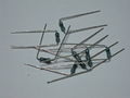
the three resistors
-
If you want to be accurate, make sure the distance between the bends is 11 mm.
-

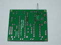
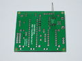
board with placed resistors
-
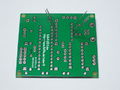
backside view
-
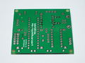
backside after soldering
-
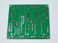
after clipping away the excess leads


USB Zener Diodes

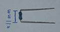
Additionally, we need two 3.6 V Zener diodes for the data lines, Z1 and Z2. Here, you have to pay attention to their orientation. The (black) line on the diode is the same as the single line on the symbol (as opposed to the triangle) that is printed onto the PCB. You can see that in the figure on the left.
The solder process looks just like the one of the resistors, but this time, if you want to be accurate, you have to bend the diode legs so they are 7.5 mm apart.
-
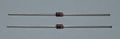
the two Zener diodes
-
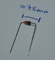
this time, the distance between the leads is 7.5 mm
-
PCB with the diodes placed
-
back side
-
back side after soldering
-
back side after clipping


Reset Resistor

The Reset pin gets a 10 kOhm resistor R12 to the 5 V line. Again, have a look in the table for the correct color markings. Orientation is irrelevant.
| Name | Value | Color Code |
|---|---|---|
| R12 | 10 kOhm |  (brown-black-black-red-brown) (brown-black-black-red-brown)
|
-
the reset resistor...
-
...placed and soldered

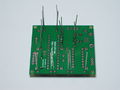
Column Resistors

If you bought a kit or attend a workshop, you probably already got the correct Resistors. There should be (at least) nine of the same value. Just solder them into the places for R1 to R9.
If you are supplying your own LEDs or did not get matching resistors for any other reason, you have to pay attention: The ideal column resistors should be chosen for each LED color separately. You are always on the safe side, if you choose a high value, but then your cube may not be as bright as you want it to be. If you are interested in this, read LED Cube/Column Resistors in Detail. Alternatively, here is a table of common colors, their forward voltages and the recommended resistor value:
| Color | Forward Voltage |
Resistor Value (nearest @15 mA) |
Color Code |
|---|---|---|---|
| Red | 1.9 V | 120 Ohm |  (?-?-?-?-?) (?-?-?-?-?)
|
| Blue | 3.0 V | 58 Ohm | Datei:R-58.jpeg (?-?-?-?-?) |
| White | 3.0 V | 58 Ohm | Datei:R-58.jpeg (?-?-?-?-?) |
-
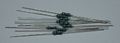
the (example) resistors...
-
...after bending,
-
...placing, ...
-
...from the back, ...
-
...and after soldering and clipping.


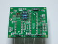
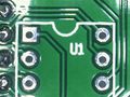
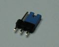
Column and Plane Connectors

Now add the column and plane connectors to CONN1 to CONN10. This step is optional and it is probably the most annoying part of this PCB, but you should think twice before you skip it: It allows you to disconnect and reconnect your cube without expensive equipment. And do repairs on it which may not be possible while it is connected. But it's your choice - skipping this step does not have any other significant effect.
So, to add the connectors, we first have to separate them from the break-away header row. You can do this with a scalpel or side cutters. You will need nine single-pin connectors and one 3-pin connector. You can also completely remove the plastic around them if you want. Now put one by one into the pcb, and solder them. You do not have to cut away any excess wire afterwards. You may however try to reheat some solder joints and wiggle on them, if the connectors are not straight.
-
the first plane connector in the top right corner
-
the same connector now in the top right corner
-
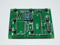
after soldering of all connectors


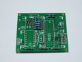
Capacitors
We need four capacitors, two times 100 nF (C1, C2) and two times 22 pF (C3, C4). See the schematic at the left or the table below for their values and positions. Again, all four devices are symmetric and orientation is irrelevant.

| Name | Value | Marking |
|---|---|---|
| C1 | 100 nF |  (104 ≙ 10 * 10^4 pF = 100 nF) (104 ≙ 10 * 10^4 pF = 100 nF)
|
| C2 | 100 nF | (104 ≙ 10 * 10^4 pF = 100 nF)
|
| C3 | 22 pF |  (220 or 22 ≙ 22 * 10^0 pF = 22 pF) (220 or 22 ≙ 22 * 10^0 pF = 22 pF)
|
| C4 | 22 pF | (220 or 22 ≙ 22 * 10^0 pF = 22 pF)
|
-
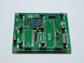
The PCB with the capacitors soldered into it.

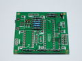
Crystal
Now you should add the 16 MHz crystal U3. You do not have to care about its orientation.
-
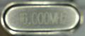
16 MHz crystal
-
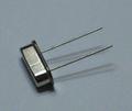
16 MHz crystal
-
PCB with crystal


Transistor Array
Now add the transistor array U2.

But first we have to make sure it fits. If you have a look at the following picture you can clearly see that the way the IC got deliviered to you, has pins that are tilted:

To get them straight, take the IC with both hands and put it on a flat surface. Then slowly bend it forward until the legs are straight.

Now you see that it fits.

Before soldering, make sure that the notches are correctly aligned. You will find one on the IC itself and one on the PCB.

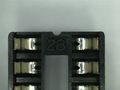
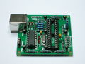
Microcontroller socket
Add the microcontroller socket to the PCB at U1. As with the Transistor array, there is a small marker on the package which should be on the same side as the marker on the PCB.
-
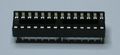
the socket
-
notch marker on the PCB
-
notch marker on the socket
-
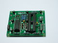
PCB with socket


USB Socket
Now add the USB socket. This should be straightforward. You should solder the two big shield connectors on the side, not just plug them in, to increase the stability.
-
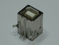
the USB Socket
-
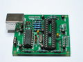
soldered (view from above)
-
soldered (view from below)


Bootloader Jumper
Now we need the bootloader Jumper CONN12.
-
The pin header with jumper...
-
and as it is soldered.
-
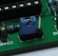
In this position, the microcontroller will start the bootloader after a power-cycle.


