LED Flower: Unterschied zwischen den Versionen
Marvin (Diskussion | Beiträge) |
Marvin (Diskussion | Beiträge) |
||
| Zeile 332: | Zeile 332: | ||
</gallery> | </gallery> | ||
The crystal oscillator then goes directly on the other side of the pcb below those two capacitors. Just put it in and solder both pins | The crystal oscillator then goes directly on the other side of the pcb below those two capacitors. Just put it in and solder both pins. | ||
<gallery widths=200px heights=200px perrow=3> | <gallery widths=200px heights=200px perrow=3> | ||
Datei:Lf-0060-00.jpeg|Position of the Crystal | Datei:Lf-0060-00.jpeg|Position of the Crystal | ||
Datei:Lf-0060-01.jpeg|From the bottom | Datei:Lf-0060-01.jpeg|From the bottom | ||
Datei:Lf-0060-02.jpeg|Solder both pins | Datei:Lf-0060-02.jpeg|Solder both pins | ||
</gallery> | |||
Then clip of anything that is above the solder joint. | |||
<gallery widths=200px heights=200px perrow=3> | |||
Datei:Lf-0060-03.jpeg|Clip off the excess wire | Datei:Lf-0060-03.jpeg|Clip off the excess wire | ||
</gallery> | </gallery> | ||
Version vom 25. Dezember 2010, 17:15 Uhr
PCB


BOM
Necessary
| Designator | Value | Part-No | Price / EUR | Count | Sum / EUR |
|---|---|---|---|---|---|
| R1 | 3.6 kΩ, 1206 | R: | 0.01 | 1 | 0.01 |
| R2 | 2.7 kΩ, 1206 | R: | 0.01 | 1 | 0.01 |
| R3, R4 | 68 Ω, 1%, 1206 | CSD: 10-120068 | 0.01 | 2 | 0.02 |
| R5..R19, R38..R40 | 3.6 kΩ, 1206 | R: | 0.01 | 18 | 0.18 |
| R20..R31 | 100 Ω, 1206 | R: | 0.01 | 12 | 0.12 |
| R32..R37 | 150 Ω, 1206 | R: | 0.01 | 6 | 0.06 |
| B1..B3 | 0 Ω, 1206 | R: | 0.01 | 3 | 0.03 |
| T1..T18 | BC807-25, SOT23 | R: BC 807-25 SMD | 0.04 | 18 | 0.72 |
| C1, C2, C3 | 100 nF, 16 V, 0603 | R: X7R-G0603 100N | 0.05 | 3 | 0.15 |
| C4, C5 | 22 pF, 0603 | R: NPO-G0603 22P | 0.05 | 2 | 0.10 |
| C6 | 10 uF, 10 V, 0805 | R: X5R-G0805 10/16 | 0.07 | 1 | 0.07 |
| C9 | 100 nF, 63 V, 1206 | R: X7R-G1206 100N | 0.05 | 1 | 0.05 |
| D2, D3 | 3.6 V Zener Diode, MiniMELF | R: SMD ZF 3,6 | 0.05 | 2 | 0.10 |
| X1 | 20 MHz | R: 20,0000-HC49U-S | 0.18 | 1 | 0.18 |
| ISP, ADC, PWR | 12-pin break-away connector (from a 36-pin strip) | R: SL 1X36W 2,54 | 0.27 | 1 | 0.27 |
| CONN_USB | USB B connector | R: USB BW | 0.21 | 1 | 0.21 |
| U1 | ATmega88-20AU | R: ATMEGA 88-20 AU | 2.95 | 1 | 2.95 |
| LED1..LED6 | RGB LED | ? | 0.30 | 6 | 1.80 |
| 24 Copper wires | 40 cm copper wire cutoff | R: CUL 500/0,63 | 13.90 | 0.058 | 0.81 |
| Sum | 7.84 | ||||
Version 1: USB Powered
| Designator | Value | Part-No | Price / EUR | Count | Sum / EUR |
|---|---|---|---|---|---|
| L1 | 10 uH, 450 mA, 1210 | CSD: 146-121R010 | 0.22 | 1 | 0.22 |
| U2, C7, C8 | Do not populate | 0.00 | 0 | 0.00 | |
| Sum | 0.22 | ||||
Version 2: Externally powered
| Designator | Value | Part-No | Price / EUR | Count | Sum / EUR |
|---|---|---|---|---|---|
| U2 | LM1117-5.0 | CSD: LM1117DT-5,0V | 0.95 | 1 | 0.95 |
| C7, C8 | 10 uF, 10 V, 0805 | R: X5R-G0805 10/16 | 0.07 | 3 | 0.21 |
| D1 | 1N4001, MELF | R: X7R-G1206 100N | 0.04 | 1 | 0.04 |
| L1 | Do not populate | 0.00 | 0 | 0.00 | |
| Sum | 1.20 | ||||
Option: Button
| Designator | Value | Part-No | Price / EUR | Count | Sum / EUR |
|---|---|---|---|---|---|
| R41 | 3.6 kΩ, 1206 | R: | 0.01 | 1 | 0.01 |
| BTN | Pushbutton | ? | 0.10 | 1 | 0.10 |
| Sum | 0.11 | ||||
Tutorial
Soldering the Components onto the PCB
Microcontroller
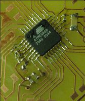
The first step in soldering this board is also the most difficult: Soldering the microcontroller. We are going to use the drag soldering technique. To do so, we first place the microcontroller on the board to get an idea of how it should be placed afterwards. Note the pin one mark which is a small dip in one corner of the IC. This is used to orient it correctly:

Now remove the microcontroller again, select one pad of the pcb and tin it. For this and the next two steps, you don't have to worry about any solder bridges, we will remove them afterwards.


Now grab the microcontroller with a pair of tweezers, heat up the tinned pad and place the microcontroller correctly. Do not overheat the microcontroller: If you are not able to position the microcontroller within about 10 seconds remove the soldering iron and try again after waiting a short amount of time.


To further secure it, also solder one pin on the opposite corner.


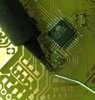
Now select one edge of the microcontroller that has not been used in the previous steps and add some Flux to pins. What comes now is not easy and probably may require multiple attempts: Solder some pins one on side of the edge at once and then just slide the soldering iron slowly and without any pressure to the other side:


If you have done everything right (right speed, correct amound of solder and flux) all pins will be soldered to the board and there will be no bridges between them:

If you have created any bridges, there are two ways to get rid of them:
- Drag the solder away from the microcontroller.
- Use a desoldering gun or desoldering wig.
However, repeat this process for the three other edges that are not yet soldered completely:

Decoupling Capacitors
To operate, the microcontroller needs a set of decoupling capacitors. These are two-padded components, so we will esentially replicate the first steps of the microcontroller soldering process:
- Tin one pad,
- add the component and
- solder the other side.
The first one is C9, a 100 nF capacitor in a 1206 package, the biggest of the capacitors included in this kit:


Now continue with C1 using the same process. C1 is also a 100 nF capacitor, but in a 0603 package.


And now C2 and C3, both the same capacitor as C1.


Crystal Oscillator
Next step is the crystal oscillator. To prepare for that, we will first solder the capacitors C4 and C5 which are both 22 pf 0603 capacitors.


The crystal oscillator then goes directly on the other side of the pcb below those two capacitors. Just put it in and solder both pins.
-
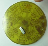
Position of the Crystal
-
From the bottom
-
Solder both pins


Then clip of anything that is above the solder joint.
-
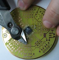
Clip off the excess wire
